
The 3000 Forum
trafficator relay
Posted by bava


|
Topic Creator (OP)
Jul 16, 2020 02:02 AM
Joined 5 years ago
36 Posts
|
|
G'day all,
I intend to have separate blinker/flasher lights on my BT7. Does anyone have a wiring diagram on how to join the wires and remove the flasher relay box completely (the 8 terminal box mounted on the guard.
I have found one for MGAs but the wiring is slightly different.
Cheers
Bryn
I intend to have separate blinker/flasher lights on my BT7. Does anyone have a wiring diagram on how to join the wires and remove the flasher relay box completely (the 8 terminal box mounted on the guard.
I have found one for MGAs but the wiring is slightly different.
Cheers
Bryn
|
TinCanA
Andrew B
|
Jul 16, 2020 04:24 AM
Joined 10 years ago
23 Posts
|
G'day Bryn,
Have a look at MGAGuru. MGA 1500's use the same relay. http://mgaguru.com/mgtech/electric/ts201.htm
Andrew
Have a look at MGAGuru. MGA 1500's use the same relay. http://mgaguru.com/mgtech/electric/ts201.htm
Andrew
 |
Jul 16, 2020 02:08 PM
Joined 12 years ago
1,139 Posts
|
Hi Bryn,
Sorry but I do not have an alternative approach to replace the Flasher Relay for you. However, recently my Flasher Relay failed and I followed the directions of a friend (along with additional additions) to rebuild the unit for a small cost. The rebuild consisted of (2) 8-connector relays installed in the same platform installed with rivet nuts at the feet and attached to the inner fender with compatible screws entered via the inner fender well (made the job much easier).
Take a look and see if it is something you can use,
Ray(64BJ8P1)
Attached is a copy of my article:
Attachments:
Signaling your Intention (1).pdf 684.1 KB
 |
Jul 18, 2020 05:58 AM
Top Contributor
Joined 7 years ago
522 Posts
|
Hi Bryn,
How important is it for you to get rid of the relay box? I did this conversion on my BJ7 10 years ago and decided it was simpler to keep the existing wiring and relay box, which serves as a junction box, but disable the relay function. The simple answer to your query is to follow the late series BJ8 wiring diagram, but using the existing wiring and relay box makes it simple IMHO. The essence of what I did was:
1. Disconnect the (green/purple) feed from the brake light switch from terminal 5 of the relay box.
2. Divert the brake light wires in the boot (trunk) to serve the new amber rear indicators mounted in the previous reflector nacelles. Mount new reflectors on (in my case under) the rear bumper.
3. Run a new wire connecting the disconnected brake switch wire referred to at 1 above to the boot/trunk to serve the brake lights. The side /running lights remain the same.
This leaves the relay box in place as a dormant junction box. The relay mechanism will no longer be activated by the brake light circuit.
I went a bit further with my modification as below but these steps aren't necessary:
To supplement, rather than replace, the unreliable pressure actuated brake light switch (see endless complaints on this Forum) I ran a new lead from the ignition side of the fuse box to a simple pedal actuated switch and connected this into the new brake light wire referred to above.
I replaced the front side/running light fittings with ones to take single filament bulbs and I use amber bulbs inside the frosted clear front indicator glasses. I fitted new headlamps with integral side/running lights which give low level illumination of the whole of the headlamps.
For once, I don't think any photos would help.
Ray: many thanks for posting your excellent and very useful "illuminating" advice sheet which I have filed for future reference. Bill
|
Topic Creator (OP)
Jul 18, 2020 09:40 PM
Joined 5 years ago
36 Posts
|
|
G'day all,
Thank you Andrew Ray & Bill, Great article Ray . Thanks Bill you used all my ideas ten years ago! But I really wanted to get rid of the relay box as I have fitted a/c , electric water pump & electric fan behind the radiator & it's a bit busy in that area.
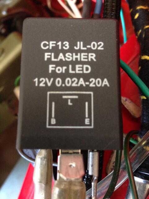
Here's what I finished up with, Using the MGA site that details the wiring I was having trouble working out the power wire it turns out the fifty year old canister was not working nothing lasts does it! But now all good, I am using a LED in the dashboard repeater so I needed a flasher can that did both types of globes for the moment this one in the picture from the local electronics shop does both. Being colour blind in red & green makes for a lot of drama doing the wiring have to keep getting my wife to keep checking the wires lol!
Anyway as the picture shows all the wires have ben soldered & connected & system works! Except! when I turned off the flashers the repeater on the dash keeps going regardless of the switch. I have read stuff about power bleeding across to LEDs so will follow that up.
I piggy backed the repeater wire onto the output wire. the unused green power wire from the fuse block I used as a green/brown wire to the switch to save running a new wire as the MGA site tells you to do. The brake wire from the loom I will run to the rear for brake lights, have yet to find out if the hydraulic brake unit works but will change it to one like yours Bill.
Thanks again guys for your help
Cheers
Bryn
Thank you Andrew Ray & Bill, Great article Ray . Thanks Bill you used all my ideas ten years ago! But I really wanted to get rid of the relay box as I have fitted a/c , electric water pump & electric fan behind the radiator & it's a bit busy in that area.
Here's what I finished up with, Using the MGA site that details the wiring I was having trouble working out the power wire it turns out the fifty year old canister was not working nothing lasts does it! But now all good, I am using a LED in the dashboard repeater so I needed a flasher can that did both types of globes for the moment this one in the picture from the local electronics shop does both. Being colour blind in red & green makes for a lot of drama doing the wiring have to keep getting my wife to keep checking the wires lol!
Anyway as the picture shows all the wires have ben soldered & connected & system works! Except! when I turned off the flashers the repeater on the dash keeps going regardless of the switch. I have read stuff about power bleeding across to LEDs so will follow that up.
I piggy backed the repeater wire onto the output wire. the unused green power wire from the fuse block I used as a green/brown wire to the switch to save running a new wire as the MGA site tells you to do. The brake wire from the loom I will run to the rear for brake lights, have yet to find out if the hydraulic brake unit works but will change it to one like yours Bill.
Thanks again guys for your help
Cheers
Bryn
Forums 
Having trouble posting or changing forum settings?
Read the Forum Help (FAQ) or contact the webmaster