


Monitoring product quality on welded tube, pipe mills
Sensors, software, other advancements allow less-skilled operators to do more than ever before
Methods for monitoring the welding process on tube and pipe mills for inline quality control continue to become more capable with less reliance on skilled operators.
Welding mills for tube or pipe production are anything but simple. The steel has to be uncoiled, formed, welded, quenched, straightened, and cut to length, and each of these actions has to be coordinated and integrated so the entire process runs like a single, smooth-running operation to make good product. Getting everything dialed in to establish a consistent, stable process is a continuous challenge, and occasionally things go wrong.
If product evaluations are conducted only after the tube or pipe comes off the mill, things could go wrong for a long time and nobody would notice until it was too late. No tube or pipe producer wants to make a large pile of scrap, or a small one for that matter; monitoring the processes on the mill and evaluating the tube or pipe as it’s made can go a long way in keeping scrap to a minimum.
That’s the difference between quality control, which is performed just before the product goes to the customer, and process control, which is done while the product is being made.
“A defect might start small and grow,” said Francois Laflamme, systems product manager for Olympus IMS. “Annealing, quenching, tempering, shaping, sizing, cutting, hydrotesting—every step has the potential to cause a defect to grow.” A quality control check can uncover such a defect when it is somewhat large, he explained, but a process control system has to be able to catch the defect early in the process.
“Its objective is to find any defects as early as possible, which means finding defects that are as small as possible,” he said.
Laflamme’s description is simple, but on a weld mill, this can be tricky. Every size changeover means the operator has to set up the test probes in the proper locations, at the necessary standoff distances, and at the correct angles relative to the material under test. Then he has to calibrate the equipment by using a sample of material with a known defect. That’s difficult to do in a challenging environment, but the relentless march of technology is making setups and calibrations easier than ever before.
Two Common Inspection Modes
Two of the common nondestructive testing (NDT) processes are eddy current and ultrasonic. Eddy current inspection uses electromagnetic principles to induce current to flow through the tube or pipe under test. Electrical current flows in much the same way as water in a stream, always taking a path of least resistance. When the water encounters an obstacle such as a rock or a log, it flows around the object and a small vortex, or eddy, forms in the water. The eddy is often visible downstream of the obstruction.
Electrical current flows freely through a conductive metal as long as the metal’s characteristics are continuous. The flow is disrupted when the characteristics of the metal change. Any such change is a discontinuity.
An ultrasonic system uses mechanical principles to accomplish something similar. As the name implies, it imparts a sound wave, one too high-pitched for human hearing, that flows through the material.
Some ultrasonic systems use a single probe, but a phased-array ultrasonic system uses several transducers. The transducers fire at various times so the signals aren’t in phase with each other. The transducers are set at various angles to send test signals in several directions, and they travel through the tube or pipe material in a variety of pathways, reflecting off of the product’s surface for maximum coverage.
Using an NDT system involves matching the signal’s frequency to the characteristics of the alloy under test and the mill’s line speed. Mechanical characteristics also come into play. Because the transmitter and receiver of an eddy current system encircle the tube or pipe, the system’s ability to detect flaws is affected by the fill factor, which is the difference between the OD of the material under test and the ID of the encircling coil. Proper centering is also a factor.
Designing and Tuning a Continuous NDT System
Using an NDT system involves matching the signal’s frequency to the characteristics of the alloy under test and the mill’s line speed. Mechanical characteristics also come into play. Because the transmitter and receiver of an eddy current system encircle the tube or pipe, the system’s ability to detect flaws is affected by the fill factor, which is the difference between the OD of the material under test and the ID of the encircling coil. Proper centering is also a factor.
Mill alignment and maintenance affect results as well. If the mill components aren’t aligned, the mill’s drive system has an aging or failing bearing, or the cutoff blade is somewhat dull—sending a massive shock through the tube every time it cycles—the noise they created travels through the pipe. The NDT system’s receiver is tuned to the signal provided by the transmitter; the noise in the background makes this akin to listening to a distant AM radio station through competing static. In the case of the tube mill, the transmitted signal might be overwhelmed by background noise.
Optimizing all of the test and mill characteristics improves the signal’s strength and reduces the background noise. Improving the signal-to-noise ratio improves the flaw detection capability.
Getting the Signal from Here to There
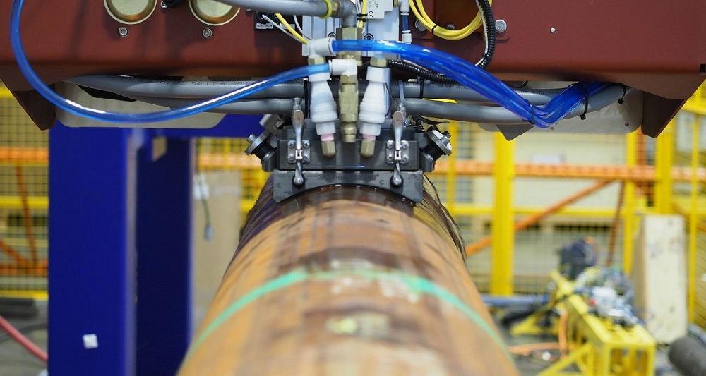
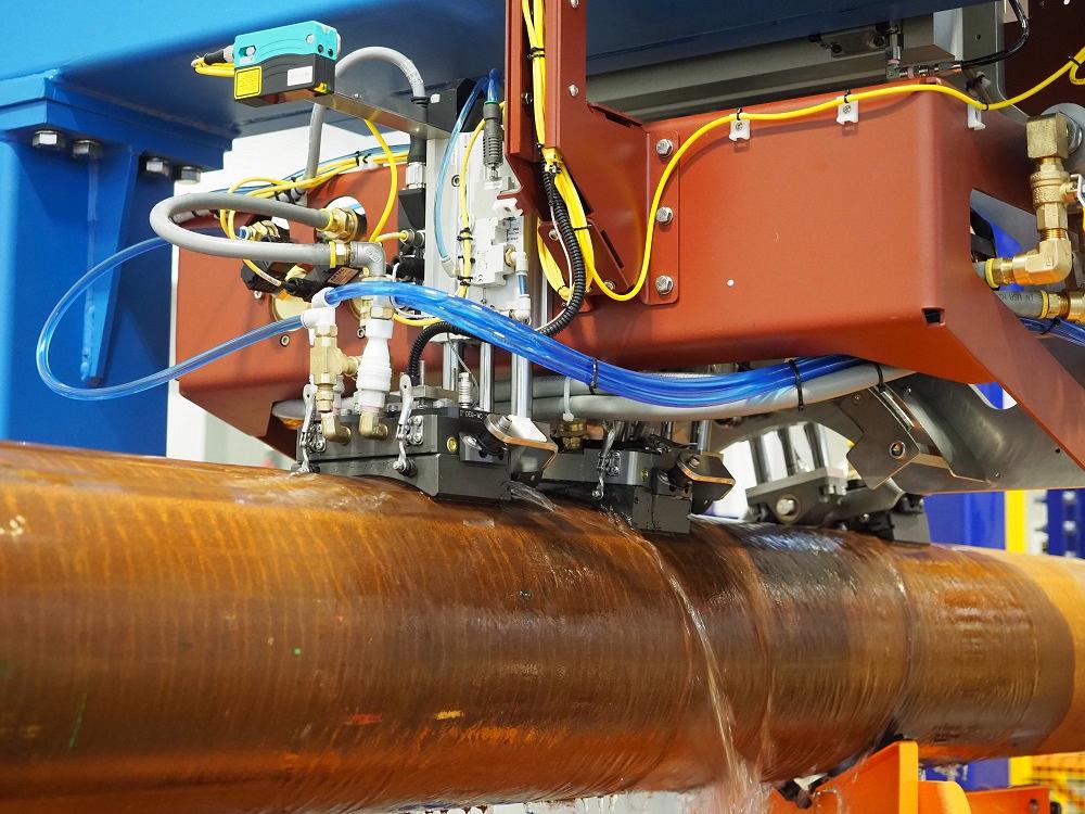
The transmitter and receiver can be separate units, an arrangement called pitch and catch, or they can be a single unit that sends a signal and detects the return signal, pulse and echo. In either case, changing from one production run to another is a matter of changing the NDT hardware and getting everything properly located and aligned.
A traditional changeover used to involve removing, replacing, and manually adjusting several blocks outfitted with the NDT components. Olympus has simplified this process with a device it calls a water wedge. It’s a single mechanical assembly outfitted with the NDT hardware located in fixed positions and installed at the correct angles. Shaped like a fork or a yoke, it straddles the tube or pipe, and its wear plate—a carbide strip—rides on the surface of the material under test. When changing from one product run to the next, the operator removes the water wedge and replaces it with a water wedge that corresponds to the next product run. The water wedge provides just a little latitude for precise positioning—vertical and yaw—and after it’s set, it holds all the inspection hardware in the proper positions. Replacing the wear plate takes just 5 seconds or so, Laflamme said.
The calibration is fully automatic; the operator makes no adjustments. To begin the calibration sequence, the operator uses the interface to put the system into the calibration mode, then runs a calibration sample through the system. The sample is a pipe with a known defect—say, a hole of a specific diameter drilled through the wall or drilled only partway through the wall—and when the system is finished with its evaluation, the operator accepts the calibration and is ready to start making pipe.
The operator later verifies that the calibration is still valid by running the original sample through the NDT unit. If he finds the same defect in the same location and the signal strength is unchanged, he proves that the system is still properly calibrated and hasn’t drifted through his shift. The initial calibration is calibration in. Any subsequent verifications of that setup are termed calibration out.
Connectivity
Modern recordkeeping makes it easy to store all of this information for future reference, which is especially critical for traceability and liability purposes.
Until recently, the common controller for an NDT system was a programmable logic controller, or PLC. The PLC can report the position and speed of the water wedge or other simple parameters. Olympus calls this Level 1.
Level 2 is where technology has taken industry recently. The progress of sensors and software, and the ability to turn streams of analog data into digital data and summarize that data into useful information—Industry 4.0—has changed everything in monitoring and control, allowing managers and supervisors to monitor nearly everything that goes on in a manufacturing facility. It’s not a stretch to track the location of every coil of raw material and every pipe in the facility, right down to each pipe’s length, weight, and inspection results, Laflamme said.
he NDT system’s receiver is tuned to the signal provided by the transmitter; the noise in the background makes this akin to listening to a distant AM radio station through competing static. In the case of the tube mill, the transmitted signal might be overwhelmed by background noise.
“Having so much information available was extremely rare 10 years ago, but these days it’s becoming common,” LaFlamme said. “Level 2 controls everything.”
Olympus is well aware that many brands of data collection system exist, so it provides an embedded panel interface that is agnostic, able to connect the Olympus NDT system to the customer’s software, LaFlamme said.
“The data gathered by an Industry 4.0 system can be used in many different ways,” Laflamme said. The simplest is a go/no-go gauge, he said. Other customers derive other data, such as the pipe’s thickness where the wall is thinnest, to calculate the pipe’s minimum strength. Determining the pipe’s weight and amount of ovality can yield a more precise strength calculation.
The evaluations cover more of the pipe than ever before. For example, using measurement technology for mapping an entire pipe is nothing new, providing data such as the minimum and maximum circumference and wall thickness along the entire length of the pipe. In the early days of this concept, each measurement pass was separated by a substantial gap, but these days the gap usually is as little as 2 mm, and in some cases, there is no gap.
Of course, not every pipe needs such thorough measurements.
“This is all specific to each pipe,” he said. “The necessary data varies by the application and the installation environment.” For example, the testing criteria for oil and gas pipe is more stringent than for most other products, and for offshore, it’s more stringent still.
“A longer test takes more time, but it reduces risk,” he said. “If the customer can demonstrate that a pipe poses less risk, this increases the value of the pipe.”
Doing More With Less
The trend toward doing more with less continues. The essence of every new technology is to introduce new capabilities or conveniences, and from there, nearly every update in that technology is designed to achieve the same amount of work, or more work, with fewer resources.
“There is always a concern about manpower,” Laflamme said. “Skilled workers are difficult to find and retain.” It would be one thing if the NDT system were used in a climate-controlled environment, one in which the operators would have the luxury of sitting once in a while, but welding mills aren’t like that. Not at all. The environment is industrial, and the work is arduous.
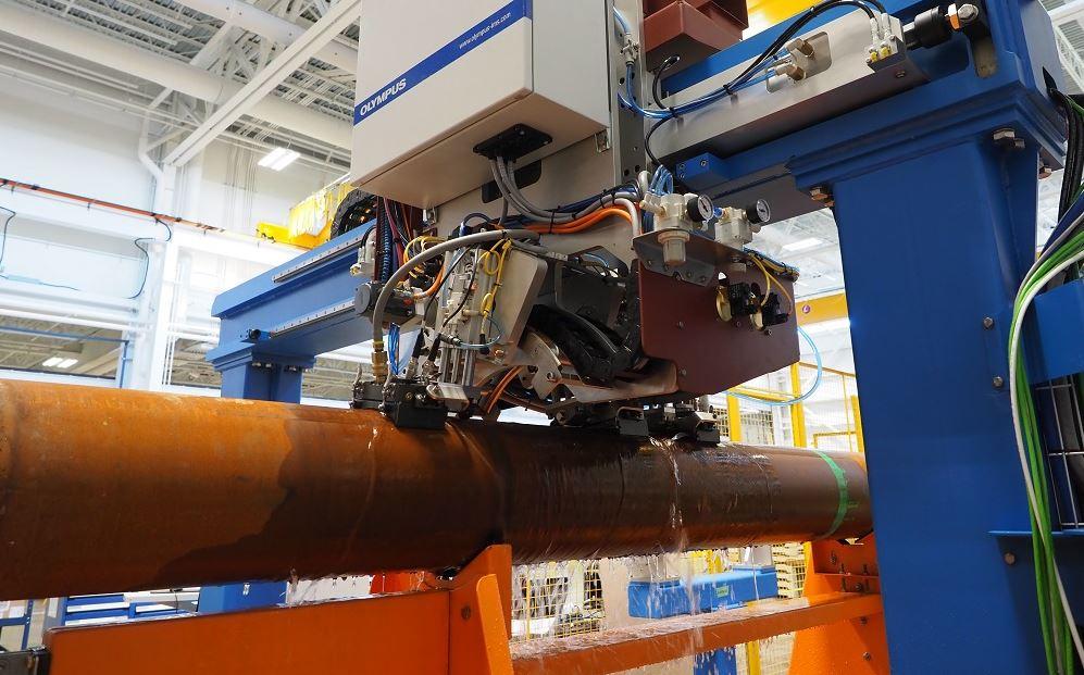
These days, a robot or a cobot can transport the water wedge and, working autonomously, use a laser scanner to align and install it. Because data management can be too much for a harried mill operator, all of it can be uploaded to the cloud and made available to engineers to analyze and provide feedback when necessary.
Laflamme acknowledges that most companies probably don’t need this level of automation and cloud-based operation right now, but these possibilities are available for those tube and pipe producers who want to take such steps.
About the Author

About the Publication

subscribe now

The Tube and Pipe Journal became the first magazine dedicated to serving the metal tube and pipe industry in 1990. Today, it remains the only North American publication devoted to this industry, and it has become the most trusted source of information for tube and pipe professionals.
start your free subscription- Stay connected from anywhere

Easily access valuable industry resources now with full access to the digital edition of The Fabricator.

Easily access valuable industry resources now with full access to the digital edition of The Welder.

Easily access valuable industry resources now with full access to the digital edition of The Tube and Pipe Journal.

Easily access valuable industry resources now with full access to the digital edition of The Fabricator en Español.
- Podcasting

In this episode of The Fabricator Podcast, Caleb Chamberlain, co-founder and CEO of OSH Cut, discusses his company’s...
- Trending Articles
1
Zekelman Industries to invest $120 million in Arkansas expansion

2
3D laser tube cutting system available in 3, 4, or 5 kW

3
Corrosion-inhibiting coating can be peeled off after use

4
Brushless copper tubing cutter adjusts to ODs up to 2-1/8 in.

5
HGG Profiling Equipment names area sales manager
