


Air-formed bend radii, magnetizing press brake tools, and more
Metal bending guru answers questions from press brake operators and fabricators
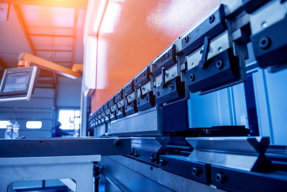
romaset/iStock / Getty Images Plus
I’ve been working through my backlog of reader questions—I still have a couple of columns’ worth before I’m all caught up again. If you have sent me a question and I haven’t answered yours yet, hang in there; your question may be next. On that note, let’s get to the questions.
Predicting the Inside Bend Radius
Question: We are trying to select tooling that will give us a 0.09-in. radius. I have kicked out a bunch of parts to test; my goal is to use the same punch on all of our materials. Could you please teach me to predict the bend radius using a 0.09-in. punch radius?
Answer: If you’re air forming, you can predict the bend radius by multiplying the die opening by a percentage value based on the material type. Each material type has a range of percentages.
60,000-PSI mild cold-rolled steel (baseline material): 15% to 17%
50 series aluminum: 10% to 12%
Hot-rolled pickled and oiled (HRPO): 14% to 16%
304 stainless steel: 20% to 22%
To find the percentage for other materials, you can compare their tensile strength with the 60,000-PSI tensile strength of our baseline material, mild cold-rolled steel. For example, if the tensile strength of your new material is 120,000 PSI, you can estimate that the percentage will be twice that of the baseline, or approximately 32%.
Let’s start with our baseline material, mild cold-rolled steel with a 60,000-PSI tensile strength. This material air-forms an inside radius that’s between 15% and 17% of the die opening, so we would usually start with 16% for our working value. The range is due to the inherent variations in the material, thickness, hardness, tensile strengths, and yield strengths. These material characteristics all have a tolerance range, which makes an exact percentage impossible to find. No two pieces of material are the same.
Considering all this, you start with the median value of 16%, or 0.16, and multiply that by the material thickness. So, if you’re forming A36 material over a 0.551-in. die opening, your inside bend radius should be about 0.088 in. (0.551 × 0.16 = 0.088). You’d then use the 0.088 as your expected inside bend radius value that you’d use in your bend allowance and bend deduction calculations.
If you get your material consistently from the same vendor, you’ll be able to find a percentage value that may get you closer to the inside bend radius you achieve. If your material comes from several different vendors, it would be best to stay with the median value for your calculations, as the material properties can vary quite a bit.
If you want to find a die opening that will produce a specific inside bend radius, you can reverse the formula to read:
Die opening = Inside bend radius/Material percentage
Die opening = 0.088/0.16 = 0.55 in.
From here, you choose the closest available die opening. Note that this assumes that the inside bend radius you want to achieve is reasonable for the material thickness you’re air-forming. For optimal results, try choosing a die opening that produces an inside bend radius close or equal to the material thickness.
When you take all this into account, the die opening you select will produce the inside radius. Also, ensure that the punch radius does not exceed the floated air-formed bend radius in the material.
Remember that there is no perfect way to predict the inside bend radius, considering all the material variables. Using these die-width percentages is more of a rule of thumb that is reasonably accurate. Still, some messaging of the percentage value may be necessary.
Tools Becoming Magnetized
Question: I have recently had a couple of inquiries about the potential of press brake tools becoming magnetized. Though we have not noticed this happening to our tools, I am curious about the severity of the concern. I can see that if a die became magnetized severely enough, workpieces could “stick” to the die and not form consistently from one piece to the next. Beyond this, are there any other concerns?
Answer: The bolster—or holder that holds the die and interfaces with the bed of the press brake—usually doesn’t become magnetized. This doesn’t mean that the bolster couldn’t become magnetized; it’s just not likely to happen.
Even so, there are thousands of ways small bits of steel can become magnetized, be it a sliver from the punching process or a radius gauge. How severe of a problem can this be? Pretty severe. Why? That small piece of material, if not found in time, will end up embedded into the working surface of the bed, creating a weak spot. If the magnetized piece is thick or large enough, it can force the bed material to rise up around the edges of the embedded piece, further keeping the bolster from sitting evenly or level, which in turn affects the quality of the parts being produced.
Formula for Sharp Bending
Question: In your article, “How an air bend turns sharp,” you mention a formula: Punching tonnage = Land area × Material thickness × 25 x Material factor. Where does the 25 come from in this equation?
Answer: That formula, which is from Wilson Tool, is used to calculate punching tonnage and had nothing to do with forming; I adapted it to be used as a rule of thumb for determining where a bend turns sharp. That 25 value in the formula references the yield strength of the material used when the formula was devised. Incidentally, that material is no longer produced but was close to A36 steel.
Of course, there is much more to precisely calculating exactly where a bend turns sharp and where the punch tip creases the bend line. The length of bend, the surface area of interface between the punch nose and the material, and even the die width all play a role. Depending on circumstances, the same punch nose radius in the same material could produce both a sharp bend and a perfect bend (that is, one with a predictable inside radius without a crease on the bend line). You’ll find a great sharp-bend calculator on my website that takes all of those variables into account.
Figuring the Bend Deduction From the Die Opening
Question: Is there a formula for back-figuring a bend deduction from the bottom die? Sometimes our press brake guy will use a smaller V opening that we have not accounted for in our flat layout. We use the standard bend deductions.
Answer: Yes and no. Let me explain. If you are bottom bending or coining, as long as the die width is reasonable relative to the formed material thickness, the bend deduction should not change much.
If you are air forming, the inside bend radius is established by the die opening, and from there you would take the radius produced in the die and calculate the bend deduction. You can find quite a few columns I’ve written on this topic at TheFabricator.com; search “Benson” and you will find them.
For air forming to work, your engineering staff needs to develop the flat blank using a bend deduction based on the floated radius produced by the die (as described at the beginning of this article under “Predicting the Inside Bend Radius”). If your operator uses the same die as engineering designed the part to be formed over, the final part should be right on the money.
Not a Question, but an Answer
Here’s something a little less common—a little shop floor wizardry from an avid reader commenting on a column I wrote in September 2021, “Press brake strategies for T6 aluminum.”
Answer from reader: First, you write some excellent articles on sheet metal fabrication. I thank you for them. Regarding the annealing you described in your September 2021 column, I thought I’d share some insights from my experience.
When I was first shown that annealing trick many years ago, I was told to use an oxyacetylene torch with just the acetylene gas ignited and color the form line with a coating of that black soot that the solo-burning acetylene gas creates. A very dark brown to a slightly black line is all you need.
Next, turn the oxygen on and, from the opposite side of the part and from a reasonable distance away, heat that line until the colored line you just applied begins to fade and then completely disappears. That seems to be the proper temperature at which the aluminum is annealed enough to ensure a 90-degree form without any cracking concerns. You don’t need to form the part while it’s still hot. You can let it cool down and it will still be annealed. I recall doing this on 6061-T6 sheet materials up to 1/8 in. thick.
I’ve been deeply involved in precision sheet metal for more than 47 years and have always had the knack for faking my way through it. But after that amount of time, I’m not faking it anymore; I know what I’m doing! Or perhaps I’m just much, much better at faking it. Either way, I get the job done in the most cost-effective manner with few bells and whistles.
Knowledge Is for Sharing
I know a bit about sheet metal manufacturing, but I’ll also admit that I by no means know it all. It has been my honor to share my lifetime’s collection of knowledge with you.
Here’s something I also know: Collectively, all of you have vast amounts of experience and knowledge. Suppose there is some tasty trick, work habit, or just some tidbit you would like to share with your fellow readers. Please, write it down or sketch a drawing and send it to me at steve@theartofpressbrake.com.
There is no guarantee that I’ll use your email in an upcoming column, but you never know. I just might. Remember, the more knowledge and experiences we share, the better we all become.
About the Author

About the Publication

subscribe now

The Fabricator is North America's leading magazine for the metal forming and fabricating industry. The magazine delivers the news, technical articles, and case histories that enable fabricators to do their jobs more efficiently. The Fabricator has served the industry since 1970.
start your free subscription- Stay connected from anywhere

Easily access valuable industry resources now with full access to the digital edition of The Fabricator.

Easily access valuable industry resources now with full access to the digital edition of The Welder.

Easily access valuable industry resources now with full access to the digital edition of The Tube and Pipe Journal.

Easily access valuable industry resources now with full access to the digital edition of The Fabricator en Español.
- Podcasting

In this episode of The Fabricator Podcast, Caleb Chamberlain, co-founder and CEO of OSH Cut, discusses his company’s...


