


Professor and Director
Editor’s Note: Read Part II.
The stamping process evolved into the huge industry we know today before the physics of metal formability and die forming were understood and mathematically quantified. As a result, the design of draw dies historically has been based on an engineering culture of experience, intuition, and trial and error.
For example, the handbook Diemaking and Die Design by Franklin D. Jones, published in 1915, had almost no equations and no discussions of strains and stresses in sheet metal. The design approach was purely from a geometric point of view. Frank W. Wilson’s Die Design Handbook, published in 1957, included some discussions of stresses and strains, but without formability aspects. The 1990 third edition by David A. Smith focused more heavily on all three subjects.
Since that time finite element analysis incorporated in commercial software packages has become a dominant tool for the stamping industry. Even so, in practice, the culture often remains to use experience, intuition, and trial and error to determine die feature dimensions, then try out those designs using computer simulation.
In the automotive industry, the virtual computer tryout now occurs much earlier in the vehicle development process, to the great advantage of the industry. But even when the virtual tryout detects some problem, the solution to the problem is still addressed by the old experience/intuition/trial and error process, although the engineer has gained considerable “experience” from the results of the simulation.
The alternate method, described here, is to structure the problem to use the mathematical analytical formulas for sheet metal formability, friction, and kinematics, but apply them as the design evolves rather than as a check after the die design is complete. The problem-structuring eliminates the mathematical complexities intrinsic to FEA and helps the designer focus on the root causes of the problems.
This approach is different from the numerical analysis with the finite element method, which involves calculating stresses, strains, and forces for the existing die configuration. In the proposed approach, the designer assigns the strains necessary in the interior of the part to get the required performance (no splits or wrinkles, minimal springback) and then, using a spreadsheet, works outward through the part and calculates from those assigned strains the strains necessary to be imposed onto the trim line of the part. He then continues to use the spreadsheet to calculate the adjacent tooling radii, arc lengths, draw wall lengths, line lengths through the wrap, and draw beads to draw from the press the correct amount of energy and correctly focus that energy into the sheet metal at each strategic point around the perimeter of the part.
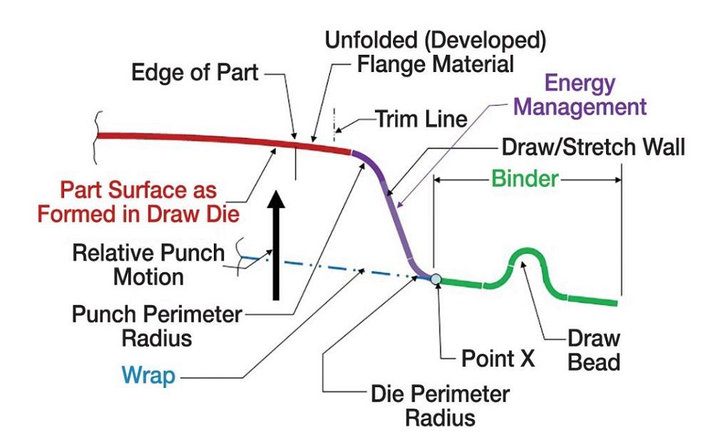
The basic elements of the sheet metal with the draw die closed on it are shown in Figure 1. The diagram illustrates the common approach of using a double-action die in a single-action press; the punch is stationed at the bottom, and the binder and the die are installed at the top.
The red line represents a section through the drawn form of the final product region. For simplicity, the product is a gently curved shape, and the downstanding pre-hem flange has been unfolded to be a simple extension of the product surface to the trim line. The phantom blue line indicates the shape of the blank after the binder has closed on it (also known as the wrap) but before the punch has engaged the sheet metal. The purple line comprises the punch perimeter radius, a nearly vertical straight section, and the die perimeter radius. The total length of these three elements is greater than the length of wrap material adjacent to them (below them in the figure).
As the die closes, it stretches these elements (along with any material being stretched off the punch) just enough to create the force on the product sheet metal (red line) to strain it the right amount. These three elements are the energy management system of the draw die. They draw the required energy from the press and focus that energy into the workpiece.
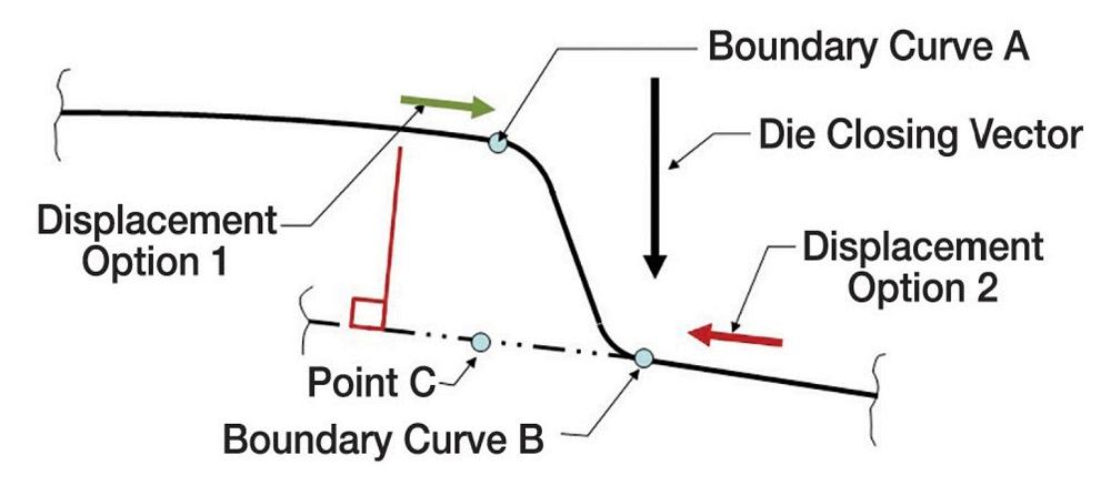
The task for the designer is to determine the dimensions of the features in the purple, green, and blue lines shown in Figure 1. To do that, he must first determine what energies must be imposed into the product sheet metal at strategic locations on the edge-of-part. For that, he should create a wireframe abstraction of the product geometry, with the wires forming circular arcs connected head-to-tail at true tangencies. There should be as many arcs as necessary to approximate the actual curvature of the product. The wires of the wireframe will have a series of features (see Figure 2) that have the same parameters as the draw wall in the purple line of Figure 1, except the dimensions are fixed by the design of the product. The die designer cannot change them.
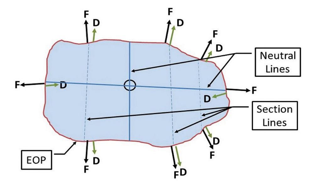
A plan view of the wireframe (see Figure 3) needs to capture the geometry of the actual product. Two of the wires, shown as solid blue in the figure, must be neutral lines and will be approximately normal to each other within the limitations of the part design. These show where the designer does not want the sliding motion of the sheet metal to slide across the die face. The sliding motion, caused by stretching or simply pulling it along, should radiate away from these lines, although it can slide along the neutral line. There will be no sliding (displacement) in any direction where the neutral lines cross. That is the “zero” point in the die. The designer uses displacement mapping to determine where these wires must be to form the part correctly. The wires must be spaced so that the sheet metal between them will form to conditions between that of the encircling wires.
In Figure 2, the length of the product feature from boundary curve A to boundary curve B is longer than the adjacent length of wrap (between boundary curve B and point C). The difference is plotted as the red and green arrows. For example, if length A-B minus length B-C is 15 mm, both the red and the green arrows would be plotted to scale at 15 mm long in the CAD data. The designer must decide if he wants the metal to slide into the feature from the direction of the red arrow, the green arrow, or some from each. His decision is his forming strategy for that feature.
For example, if the product feature under the green arrow is 500 mm long, and the other (left) end is at a neutral line, it could provide the necessary 15 mm of material by straining 3.0%. If that is what the designer decides to do, that will be his strategy. If he plans to strain the material only 2.0%, he will get only 10 mm from the green arrow side and must get the remaining 5 mm from the red arrow side. If this is what he wants, 2.0% strain will be his target strain (forming strategy) in that location. He must design the purple, green, and blue features in Figure 1 to force the target strains to happen.
This selection might depend on the sheet material and requirements for the component. For example, if the part is formed from extra-deep-drawing steel with excellent formability, more stretching may occur from the part side (green arrow), increasing the strength of the component through sheet metal work hardening. If the part is formed from ultrahigh-strength steel or aluminum alloy, the formability is more limited, and more displacement may be planned from the binder side. These considerations are addressed by the designer’s specification of the strain pair to be imposed into the interior of the panel and usually at the zero point, where the neutral lines cross.
Another factor which plays a significant role is whether the part design is driven by strength or stiffness. In the first case, stretching the sheet to achieve higher strength or employing higher-strength steel makes more sense. For stiffness-driven parts, the optimum level of stretching might be achieved using rather small stretching where material work-hardens significantly. The minimum thickness requirement is often taken into account for corrosion-critical applications, such as vehicle underbody components. The reversing of displacing direction creates a stretch-draw boundary in the feature.

Professor and Director
Oakland University Center of Advanced Manufacturing and Materials (CAMM)


The Fabricator is North America's leading magazine for the metal forming and fabricating industry. The magazine delivers the news, technical articles, and case histories that enable fabricators to do their jobs more efficiently. The Fabricator has served the industry since 1970.
start your free subscription
Easily access valuable industry resources now with full access to the digital edition of The Fabricator.

Easily access valuable industry resources now with full access to the digital edition of The Welder.

Easily access valuable industry resources now with full access to the digital edition of The Tube and Pipe Journal.

Easily access valuable industry resources now with full access to the digital edition of The Fabricator en Español.
In this episode of The Fabricator Podcast, Caleb Chamberlain, co-founder and CEO of OSH Cut, discusses his company’s...


