


Contributing Writer
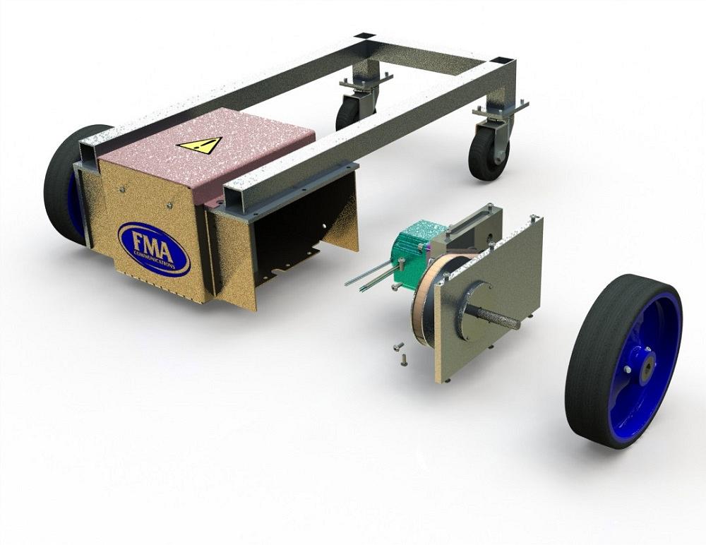
FIGURE 1. This cart is the product we’re using to discuss the setup of a CAD workstation.
Editor's Note: If you would like to download the 3D CAD files associated with this column, click here.
The FMA cart shown in Figure 1 is an ongoing CAD project that we’re using for context while explaining some of the setup chores that can be part of operating a CAD workstation.
We are in the early stages of setting up the CAD workstation for support of a product that will have a lifetime spanning years. We anticipate collaboration with other workstations and other personnel over that span of time.
Disclaimers: We’re using terminology specific to a brand of mainstream 3D CAD. The FMA cart is realistic, not real. At the time of this writing, if you want one, you must fabricate your own. You’re welcome to use the models posted with these articles as a starting point. You can find them at www.thefabricator.com/page/shop-technology-and-3-d-cad-downloads.
The goal of our workstation setup effort is to minimize tedium and reduce data entry error. The use of drop-down selection lists is our plan. Where the system doesn’t provide a selection list we like, we will create a form with a selection list that we do like.
All of the CAD workstations for this project will be set up with the same selection lists. The Copy Option Wizard is handy in that regard, but that is foreshadowing for a future column. This one-time setup work saves many keystrokes for the team over the long haul.
The previous episode’s cliffhanger (see Figure 2) pointed out that the material selection list in the Feature Manager is different from our custom form’s selection list for material.
The custom form shown to the right in Figure 2 features a drop-down list of materials. The form and its selection list of material descriptions were inherited from another project. We are going to adapt that old form to our new standards.
The form currently allows custom values for material, so any description is permitted. While the custom selection list does let us tailor the material descriptions to our standards, this Material property only works with drawing templates. Our custom Material property is not recognized by simulation software, and that’s sad.
What makes us happy is that the material specification for simulation is made using a Favorite Materials drop-down list presented by the Feature Manager, shown to the left in Figure 2. This selection list is built into the system software. We don’t have to do a thing other than use it.
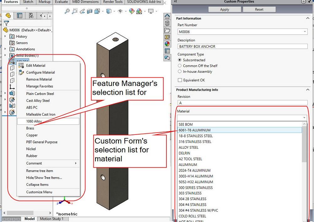
FIGURE 2. The custom data entry form (right) has a material selection list that is redundant. It does not match the system’s selection list (left) for materials.
The Feature Manager’s selection for material sets several values used by various CAD simulation tools. The model’s mass, material elasticity and strength, and material appearance are updated by this setting. A custom property is set for material—SW-Material—that will be useful to the redesign of this data entry form.
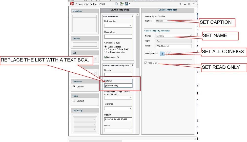
In Figure 3, Property Tab Builder is shown with the file FMA.prtprp open. The custom list for material has been deleted from our form and replaced with a text box. The text box’s Caption and Name have been changed to Material. This name change matches the expectations of the drawing template.
As we continue editing the new text box for material, the setting made regarding Configurations could allow different material for each configuration in the model. We are designing this form to have the same material apply to all configurations. That’s the reason the button is pushed, as shown in Figure 3.
The setting for Read Only makes this field a display-only item on the form. If we wanted to allow ad-hoc material descriptions to be used, we could uncheck this Read Only setting.
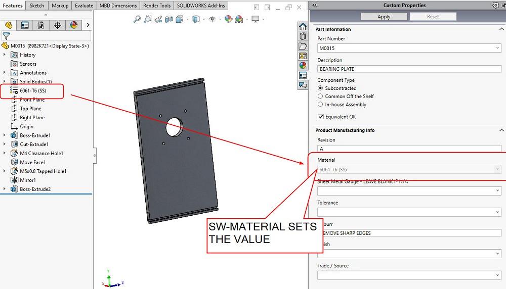
In Figure 4, the improved form is being tested. To the left in Figure 4, in the Feature Manager, the material has been set to 6061-T6 (SS). This material selection is something our CAD jockeys must do anyway. Having that one selection take care of the data entry for the material description on drawings is efficient.
Side note: The (SS) in the material description indicates that sustainability settings (SS) are included in this selection. To remove the (SS) from the description, you can create a custom material from the (SS) version and update it with your perfect description, such as 6061-T6 ALUMINUM perhaps. Include your custom material in the Favorites list, and the CAD jockeys will love you.
For this project we expect to use only a few materials—aluminum in a couple of alloys, maybe some 316 stainless steel, copper, and polycarbonate. These will be our Favorites. Other materials are allowed; they are just harder to select.
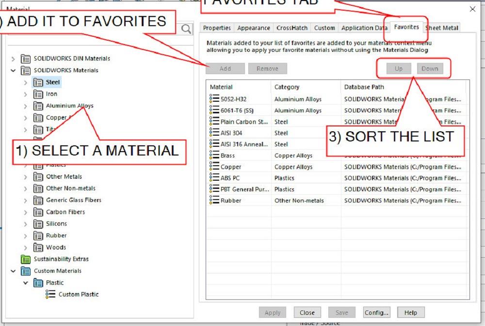
Right-mouse-button click on the Material entry in the Feature Manager, and a menu pops up with an option to Manage Favorites. Left-clicking on that option brings up something like Figure 5. There are several tabs to select from. The Favorites tab shows the current list of favorite materials. This is the selection list presented to the CAD jockey.
To add a material to the Favorites list, select the desired material from the library on the left and click on the Add button on the right. Figure 5 shows the results of editing our favorites to include some aluminum, stainless, steel, copper, brass, and plastic.
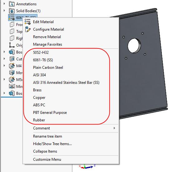
Figure 6 shows what the CAD jockey will see as a Favorites list for quick selection of material. This selection list, in combination with the data entry form on the right, is working well.
A small puzzle arises because we’re using the same drawing template for parts and assemblies. The system’s material selection list works well for parts, but material specification for assemblies isn’t always a one-line answer. We’ll address this in an upcoming episode
.


The Fabricator is North America's leading magazine for the metal forming and fabricating industry. The magazine delivers the news, technical articles, and case histories that enable fabricators to do their jobs more efficiently. The Fabricator has served the industry since 1970.
start your free subscription
Easily access valuable industry resources now with full access to the digital edition of The Fabricator.

Easily access valuable industry resources now with full access to the digital edition of The Welder.

Easily access valuable industry resources now with full access to the digital edition of The Tube and Pipe Journal.

Easily access valuable industry resources now with full access to the digital edition of The Fabricator en Español.
In this episode of The Fabricator Podcast, Caleb Chamberlain, co-founder and CEO of OSH Cut, discusses his company’s...


