


Contributing Writer
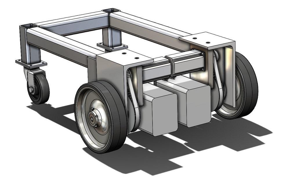
FIGURE 1A. This design was presented in the previous episode with the question “Should we proceed?” It is too tall, incomplete, and not strong enough. But, yes, we shall proceed.
Figure 1A presents a design for a motorized base for a shop cart. As a virtual prototype, this 3D model does a fair job of showing available motors and batteries that satisfy space and power requirements. The batteries and motors are selected to allow a few hours of operation while moving a fully loaded cart. The target capacity is 250 lbs.
However, the design from the previous episode has shortcomings in terms of guarding the gears and pulleys. The uneven top platform is a challenge for mounting accessories.
The evolution of this product’s design is presented here as an example of life in the CAD lane. Three-dimensional modeling up to this stage has mostly been for speed. Now the project is gaining detail. If we are going to commit to fabrication drawings, the design better not have too many more surprises in it.
We’re reviewing this to develop skills in presenting and reviewing, not necessarily building, a cart.
Here’s a CAD tip: High-resolution images with credible detail allow the audience to apply their imagination to function rather than appearance.
Figure 1B shows a couple views of a design that is nearly ready for fabrication. Sheet metal fully encloses the mechanism. The maximum elevation of this motorized base is a little lower, and the top platform allows for making attachments easier.
Recall from previous episodes that the statement of work for this project included a requirement for the steering. A remote control (RC) from the radio aircraft industry is the plan.
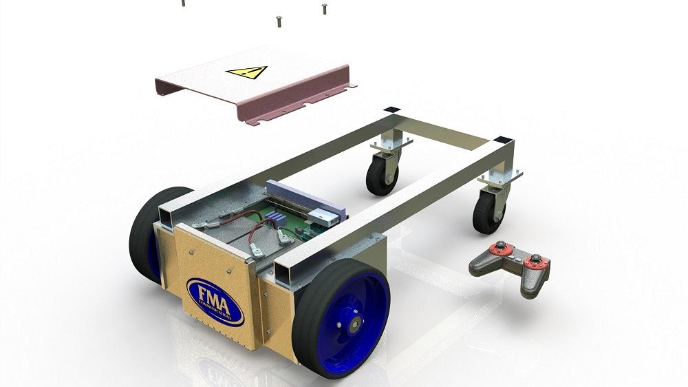
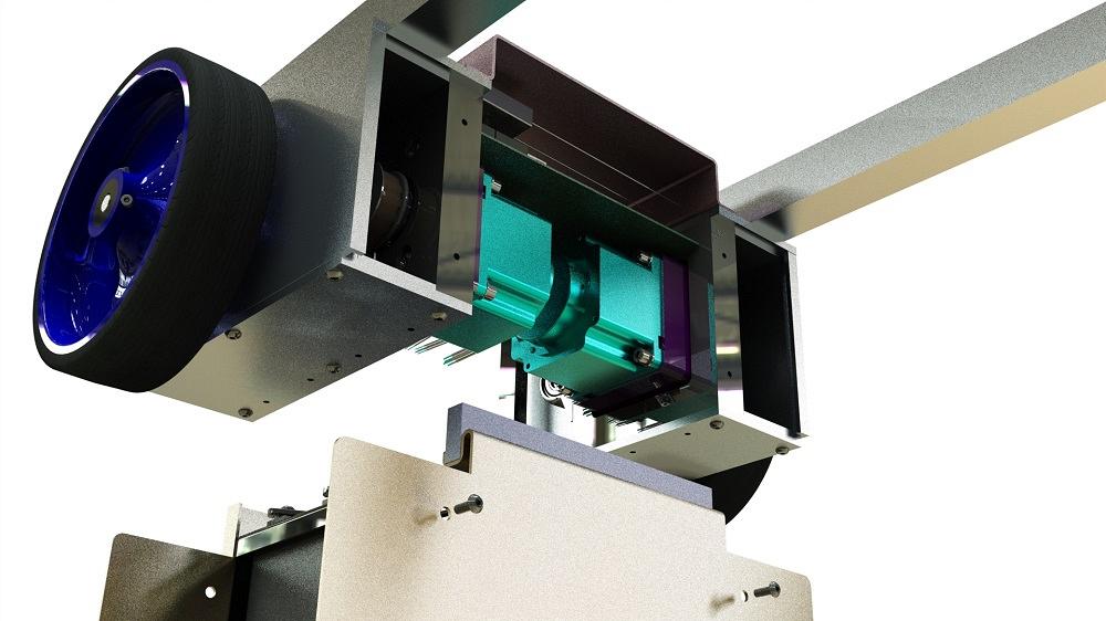
In Figure 2, an RC transmitter is included as representation of the method of steering. The matching RC receiver module and a computer for running the cart’s software are also visible inside the enclosure. The software watches the signal from the RC receiver to decide how to control the relays for the motors.
The previous design (see Figure 1A) used a common aluminum L-angle extrusion as a frame for the motor mechanism. The material was chosen for its strength and to reduce part count. What a great idea!
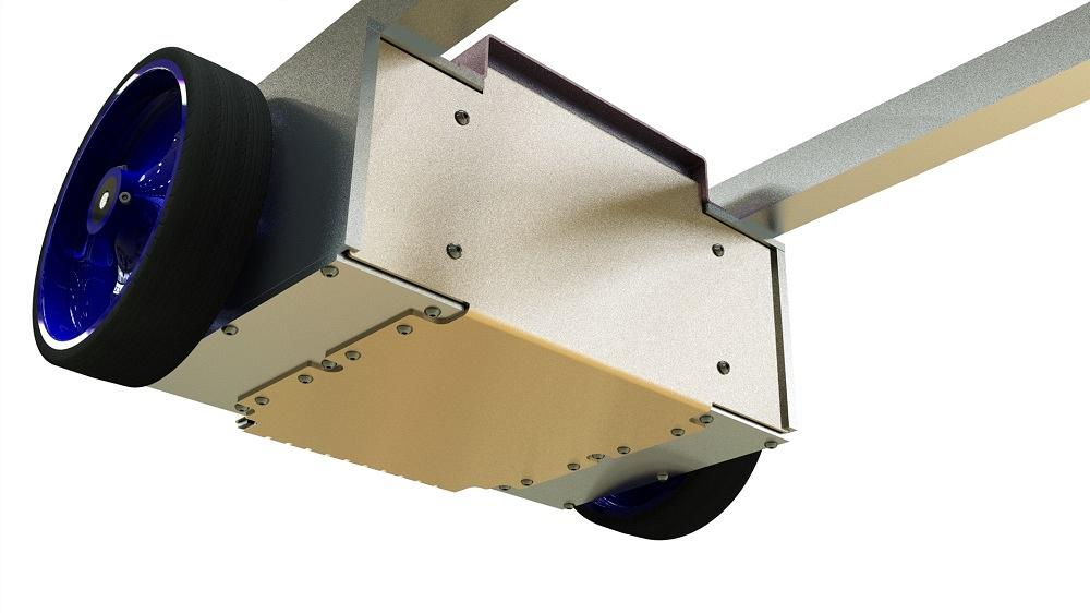
After the cost of fabrication and assembly was reviewed, the extrusion was replaced with relatively simple machined plates. In Figure 3, the new structure and orientation of the motor mechanism is shown. What a better idea!
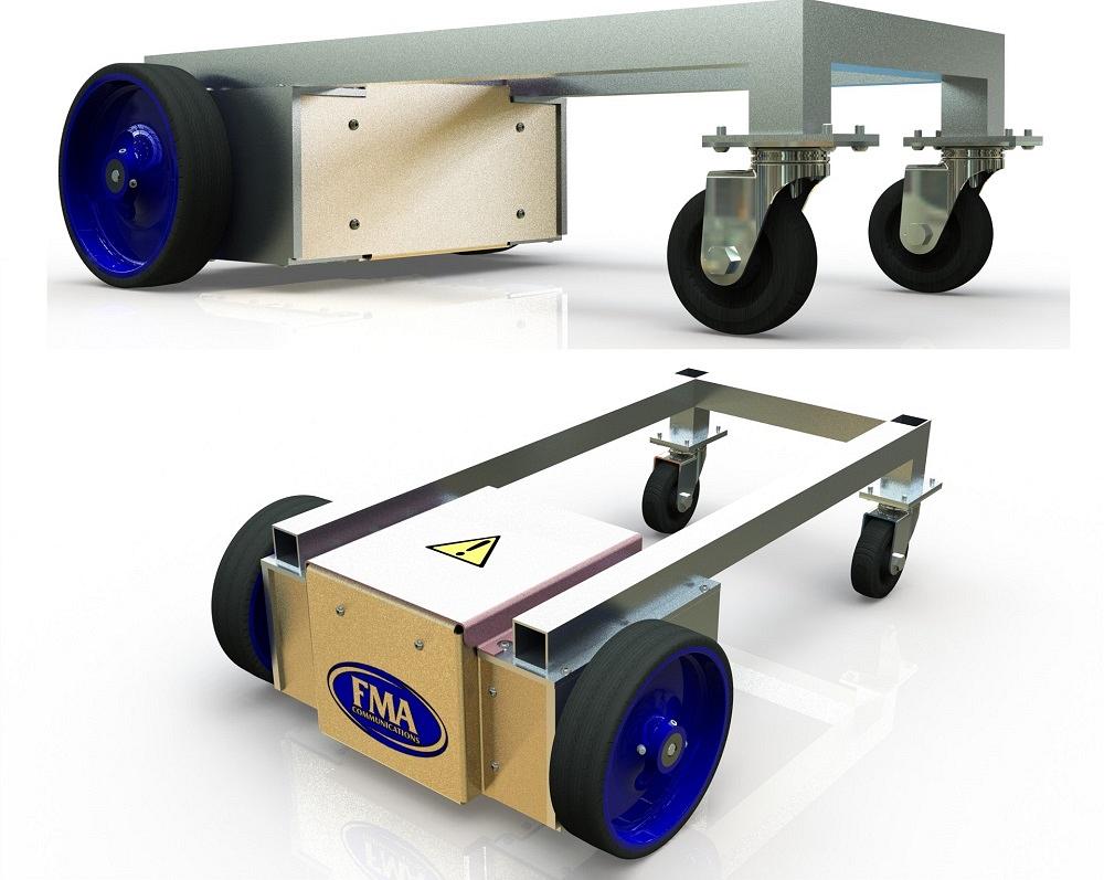
FIGURE 1B. An improved design now includes a sheet metal enclosure. The height has been reduced. The assembly is stronger and flatter for attaching accessories.
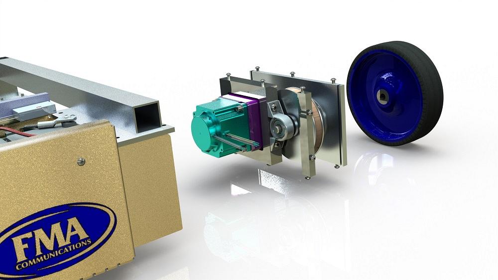
The new sheet metal enclosure is mostly a battery tray. After we remove screws on the front, rear, and bottom, it will lower and slide away (see Figure 4).
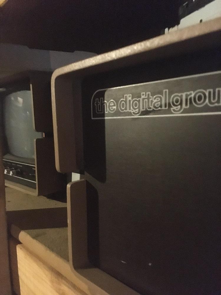
As a bit of a sidebar, in the late 1970s the homebrew computer industry was emerging. My dad’s sheet metal shop made enclosures for a company known as The Digital Group. As partners in their sheet metal job shop, Bernie Barron and my dad designed and fabricated an enclosure for Dr. Suding at The Digital Group.
Figure 5A is trying to show how the edges of the panel are hidden by the top and bottom covers. Bernie’s enclosure system used slots and slides to trap the front and rear panels in place without visible screws. The matching enclosure for the cathode ray tube monitor is lovely, an example of high-end sheet metal aesthetic.
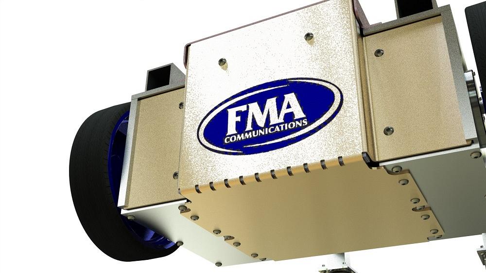
Figure 5B shows how, 50 years later, I heavily borrowed Bernie’s idea. Both gentlemen have passed, but I think they would forgive me for plagiarizing. The U-shaped sheet metal enclosure slides up into slots on the left and right edges. The screws front-and-rear pretty much lock things in place. The bajillion screws along the bottom are to take the bouncing weight of the batteries.
There is an air vent along the top, which is visible in Figure 5B. A strip of foam rubber blocks the opening as a filter. In Figure 6 we see vent holes along the bottom edge. Another strip of foam is wedged in place as a filter there.
The presentation ends with the observation that the mounting for the circuit boards is incomplete. There is no way to charge the batteries. There is no certainty that the motors will have acceptable torque and speed.
If this design is to proceed to fabrication, what are the next steps? As foreshadowing, there will be product manufacturing information—part numbers, descriptions, and activity logs. Oh my.


The Fabricator is North America's leading magazine for the metal forming and fabricating industry. The magazine delivers the news, technical articles, and case histories that enable fabricators to do their jobs more efficiently. The Fabricator has served the industry since 1970.
start your free subscription
Easily access valuable industry resources now with full access to the digital edition of The Fabricator.

Easily access valuable industry resources now with full access to the digital edition of The Welder.

Easily access valuable industry resources now with full access to the digital edition of The Tube and Pipe Journal.

Easily access valuable industry resources now with full access to the digital edition of The Fabricator en Español.
In this episode of The Fabricator Podcast, Caleb Chamberlain, co-founder and CEO of OSH Cut, discusses his company’s...


