


Senior Editor
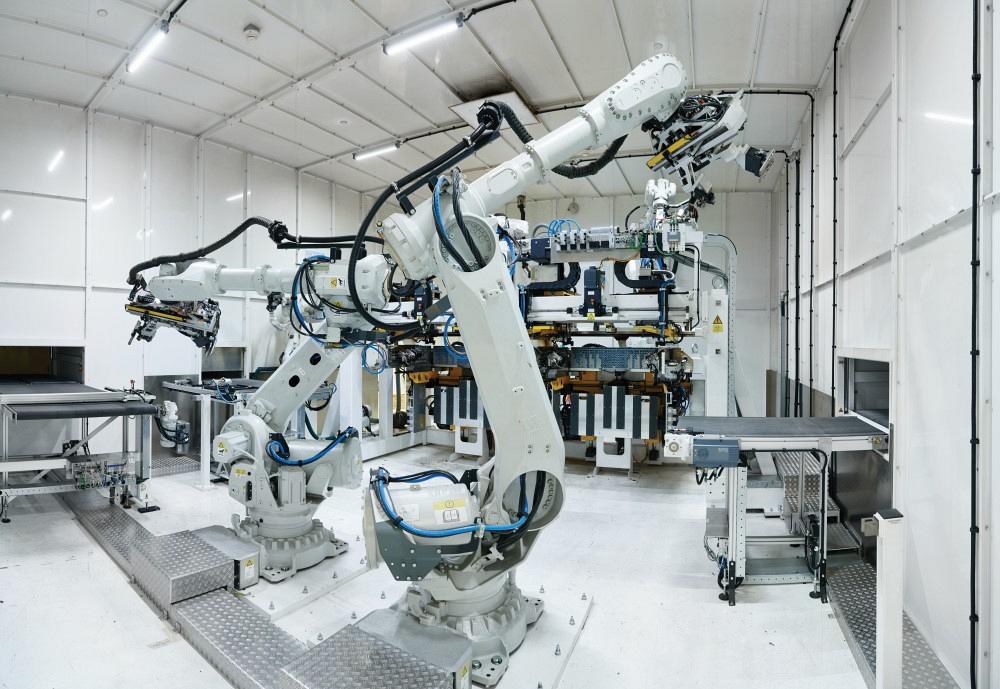
An automated cell produces laser welds that don't require or polishing.
Those unfamiliar with sheet metal would glance at the electrical enclosures produced within nVent HOFFMAN’s Anoka, Minn., facility and think nothing of them. They’re sheet metal boxes (see Figure 1), and an automated line produced them. So what? They’re simple products. If production weren’t so automated, the boxes would be made only in low-labor-cost countries, right?
Reality isn’t so simple, and neither are those electrical enclosures. In a promotional video on YouTube, the camera zooms in on one enclosure’s bottom corner after welding. It’s obviously a laser weld, and the uniformity is astounding. It certainly doesn’t need grinding or buffing.
Sheet metal shop veterans would expect to see evidence of a notch at the bottom corner, giving the necessary clearance for the two flanges to fold up. The edge between the box’s two sides looks common enough (though still eerily perfect). The joints are in a half-overlap configuration used in many a sheet metal enclosure. But the bottom corners look odd. There’s no telltale sign of a notch.
Why this is has to do with how the enclosure is designed. The corner consists of an end sheet (light gray in Figure 2) mated to the edge of another sheet (dark gray in Figure 2) bent at 90 degrees to create a half-overlap corner weld joint. And because this is a half-overlap (and not full-overlap) joint, the end sheet’s corner radii have to match not the bend’s outside radius but instead the radius at or near the bend’s neutral axis, near the middle of the sheet thickness. Considering how thin these carbon steel sheets are—some are 14 ga. and others are 16 ga.—this requirement leaves extraordinarily little room for error.
Such precision (along with sophisticated fixturing) allows a laser to weld autogenously, with the melt pool flowing to create that perfect corner, no postweld grinding or buffing required. The automated line can, depending on the enclosure sizes produced on a given day, produce nearly 1,000 of these enclosures over two shifts.
The factory doesn’t make simple boxes. On the contrary, this application exhibits precision sheet metal work at its finest, exemplifying just how far the sheet metal industry has come.
When Nick Johnson, nVent senior manufacturing engineering manager, started at the factory in Anoka in 2014, he entered a facility full of stand-alone laser cutting systems, punch presses, punch/laser combos, and rows of press brakes and welding cells.
Because the factory had its own machine design department, the facility had a fair amount of homegrown automation. For instance, the department designed an automated, gantry-mounted stud welder that could be programmed to place the necessary studs in enclosure panels. It also developed an automated graining system for buffing large stainless steel enclosures. Not a simple flat-part deburring and graining machine, the system can buff the formed and welded enclosures, corners and all, to the required finish.
Still, 2014 did represent a turning point of sorts at the Anoka factory. Many of its skilled press brake operators and welders were nearing retirement age, and managers knew those skills would be difficult to replace.
“At that time we had almost 60 positions that we just could not fill,” Johnson said. “So we looked to automation not to eliminate head count, but just to be able to make products to meet our customer demands.”
He added that those demands required that the factory produce more enclosures in less time—that is, greater throughput. At the same time, the company continued its quest to improve worker ergonomics and efficiency. All this, Johnson said, drove the factory toward more automation.
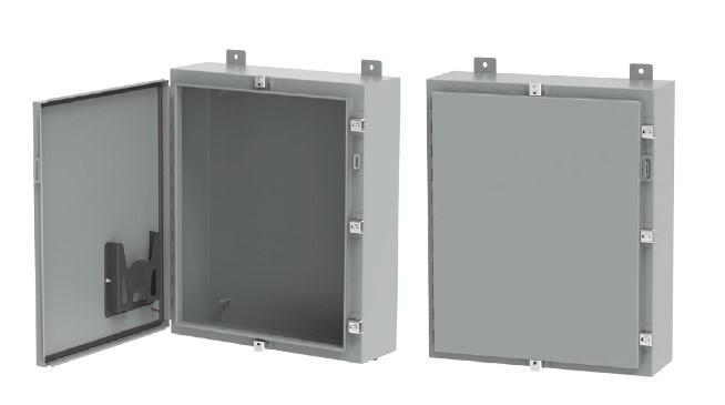
Figure 1 This wall-mounted electrical enclosure might look simple enough, but it’s anything but. The required precision approaches machining-level tolerances.
The Anoka facility produces a variety of enclosure sizes. Some enclosure models are measured in inches, while others can be up to 8 ft. tall and 10 ft. wide, with multiple access doors. Not every product was suitable for automation, of course, but some showed potential, including HOFFMAN’s wall-mounted enclosures. These product families still involved a variety of geometries, with dimensions ranging from 12 by 12 by 6 in. up to 42 by 42 by 16 in., and sheet thicknesses ranging from 16 to 14 ga. But flexible manufacturing technology had come a long way in recent years. Could production of these products be automated, and if so, how?
A team led by Travis Dahlstrom, nVent vice president of engineering, began to find answers to these questions, first by analyzing the current state of production. To no one’s surprise, welding (including manual gas metal arc welding), grinding, and polishing remained the line’s greatest bottlenecks.
“The flying sparks might make for great pictures,” Dahlstrom said, “but it’s a completely non-value-adding operation.”
Grinding is usually looked upon as a necessary task, of course, but in the early stages of their analysis, Dahlstrom and his team asked a poignant question: What makes grinding necessary? It’s the welding process, specifically gas metal arc welding. The team discovered that even robotic GMAW couldn’t eliminate all grinding.
At this point laser welding stepped into the picture. The team found that heat conduction welding could make a near-perfect corner weld. The process uses a defocused beam (the beam’s focus is slightly above the joint) to induce a melt pool that flows in such a way to create a structurally and cosmetically perfect weld.
Eliminating grinding and polishing wasn’t the only goal, however. The company also wanted to increase its material utilization in nesting. The traditional one-piece cross-shape design helped minimize the welding time—but laser welding changed the situation entirely. The laser weld didn’t require grinding, used no filler metal, and could finish a weld in a fraction of the time required by GMAW. This meant the team no longer had to worry about keeping the welding lengths as short as possible, which also meant they could alter the design of the cut blanks.
A single cross-shaped blank wasn’t their only option. Sure, nesting those cross shapes didn’t produce abysmal material yield, but the yield wasn’t great either. Many denested skeletons looked like checkerboards around the edges, showing the waste left by material between the arms of the cross.
Engineers settled on a new design involving three components: two end sheets that are welded to a single U-shaped component, which the team called the wrapper (see Figure 3).
The team uncovered a design that could increase material yield and take advantage of laser welding’s capabilities. But before moving forward, they considered all options to increase part velocity. After all, the last thing they wanted was an island of automated efficiency in an ocean of inefficiency. The company wanted to increase the velocity of work, from order release to the final shipment.
And so they asked more questions. For instance, what’s the role of material quality? Laser cutting can be extraordinarily quick, but cutting speed doesn’t matter if residual stress causes material to bow and wreak havoc on downstream processing.
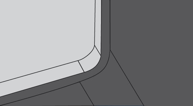
Figure 2 This close-up rendering of the enclosure’s bottom corner shows its unique design, with an end sheet (light gray) mated to the edge of a formed sheet with a 90-degree bend (dark gray). To create this half-overlap weld joint, the end sheet’s laser-cut radius must match the radius of the 90-degree bend near its neutral axis.
“We don’t buy special material for this line,” Johnson said, “but we do have an agreement that ensures [our service center’s] leveling process is very controlled. We also have material property traceability that goes back to the mills. That’s how important it is.”
Other questions involved processing options. Would it make sense to create a coil-fed line in which the work could feed continuously through all processes, from leveling and cutting to bending and welding? Space constraints would make such a system challenging to implement, though not impossible. But the team uncovered more obstacles. For instance, the product mix involved various grades and thicknesses, and the number of coil changeovers would have made the approach impractical.
Another issue involved the availability of flexible capacity. Modern fiber lasers, including the Anoka factory’s 4-kW system from Amada, have immense flexible capacity that can feed parts to various value streams, not just one automated line.
Regardless, in the factory’s current configuration, the laser—complete with a robot that stacks blanks on offloading conveyors—does mainly feed the automated line. Reliability is critical, which is why programmers cut sacrificial slugs near acute angles to ensure the blanks don’t catch during part removal.
The company partnered with two Dutch companies, AWL Techniek for the laser welding cell and WEMO for the automated bending. Both organizations became involved early in the project, well before nVent HOFFMAN settled on the enclosure’s “wrapper” redesign.
“We had known about WEMO for a long time,” Dahlstrom said, adding that some of nVent’s European operations have used WEMO lines for years. “And we knew the company worked with AWL, whom we knew as a significant laser welding player, especially in automotive.” (Editor’s note: WEMO and AWL recently formed a partnership called “From coil to cabinet,” www.coiltocabinet.com, for applications that integrate both forming and joining automation.)
Dahlstrom added, “I wanted to make sure we went with world-class, reputable players. If we put this automated system together and it didn’t work, it would have been on us.”
The engineering requirements began with the process with the most stringent requirements. “Laser welding really is the heart of the system,” Dahlstrom said. “Everything was built around it. And everything was about tolerance.”
This included cutting tolerance at the fiber laser, bending tolerance in forming, and fit-up in laser welding. The wall-mount enclosure’s bottom corner is a prime example. Again, two sheets mate to a U-shaped wrapper, and the two bottom corners have a bent radius (or, more specifically, the radius at the bend’s neutral axis) that must match precisely with the sheet’s laser-cut corner radius. The laser weld follows the U down one side, around that corner radius, across the bottom, around the other corner radius, then up the adjacent side.
To attain the weld quality they needed, they designed a half-overlap joint throughout, and the fit-up couldn’t vary by more than 30% of the material thickness. For the thinnest stock, this requirement brought the tolerance zone down to just several thousandths of an inch, or mere fractions of a millimeter—tolerances more familiar to machinists than sheet metal fabricators. This meant that the laser-cut edge, both the straight portion and the radius around the corner, had to be incredibly precise.
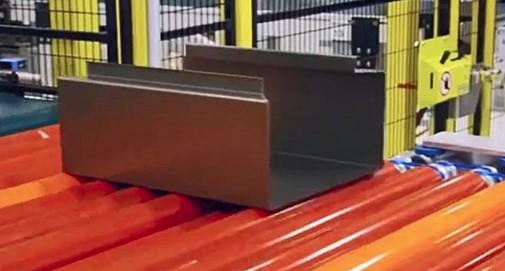
Figure 3 The enclosures were made of three components, a wrapper (pictured here) mated to two end sheets. The laser cut end sheets had to match the corners of the wrapper precisely to form a half-overlap corner joint.
Bending had to be equally precise. WEMO offers various bending units for automated lines, including CNC bending (similar to panel bending) as well as swivel bending, which uses a similar bending action as machines with bidirectional folding beams.
The company ultimately chose swivel bending because of tooling access, especially for the top 90-degree return flange with the 45-degree edge (see Figure 4). “We chose swivel bending so we could more easily access that 45-degree corner,” said Gert-Jan Engelbart, product manager at WEMO. “With swivel bending, the beam itself contacts the complete flange.” (Engelbart added that such a bend geometry is certainly possible with CNC bending; the bend sequence is just a little more complicated.)
The clamping tools in swivel bending had to hold the metal to extremely tight dimensions; even the slightest movement would push the material out of tolerance (see Figure 5).
Engineers perfected the bending and gauging sequence to reduce the effect of stackup tolerances. Every bend has a tolerance zone that compounds, or “stacks up,” with every subsequent bend. And the wrapper has eight bends: two sets of three edge flanges on the top of each leg of the U, plus the two bottom 90-degree bends (as shown in Figure 3).
“Because we need to deal with bending tolerances on both sides of the wrapper,” Engelbart said, “we bend one side first, then we use that [formed side] as a reference to bend the other side.”
The machine sets a zero point and bends one side, removes the sheet, and moves down the line to another swivel bending station. There, another zero point is set, and the swivel bending commences on the other side. This keeps the workpiece’s most critical dimension—between the two bends at the bottom of the U—well within the tolerance zone.
Of course, if you have a workpiece with eight bends and tolerances of just fractions of a degree or fractions of a millimeter, something has to give.
“The tolerances are built up from the bottom of the product upward,” said Gerbrand Rosendal, senior concept engineer at AWL. “The loosest tolerances are at the top of the product.”
He clarified that “loose tolerance” is a relative term. The forming tolerance even at the final top flanges is extremely tight and more than adequate for typical sheet metal applications. But this isn’t a typical application.
The gap between the upper flanges was too variable for autogenous laser welding. And even if the gap tolerance were tight enough, the joint design itself created complications. The half-overlap corner joint changed to a butt configuration where the return flanges mated, creating a flat surface and a secure seal between the enclosure and the closed door (as shown in Figure 1).
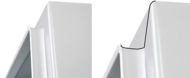
Figure 4 This shows the top corner of the enclosure, where the 45-degree cut edge of each blank mated together for welding. The added black line on the right shows the joint (invisible here, under the powder coat) that the two flanges create. That flange was one reason WEMO engineers chose swivel bending.
“Because of the way the sheets come together, there’s just no way to make an overlap at that point,” Rosendal said.
Fortunately, the remaining seam where those edge flanges joined at the top of the product wasn’t long and in an area that could be accessed by a robot arm. Ultimately, the company used a low-heat-input variation of GMAW, Fronius’ cold metal transfer (CMT) technology, to weld the final portion of the enclosure. And for this application, CMT left only a limited amount of weld metal that needed to be ground down, a task that could be handled by another set of robots on the line. Moreover, the grinding took only seconds, not minutes.
What makes the automated line stand out is just how flexible it is. Robots and other mechanization on the line use parametric programming to adjust to different enclosure sizes and sheet thicknesses. The nose of the fixed beam and clamping beams in the swivel benders adjust their position to change the bending gap for different material thicknesses (analogous to changing the die width on a press brake). These adjustments ensured the outside bend radius remained between two and three times the material thickness.
All this flexibility simplifies changeover between batches, each of which usually entails between 20 and 80 enclosures. And with every batch changeover can come a different enclosure size and material thickness.
To begin the process, a batch of blanks is placed onto loading tables. From there the wrapper blank travels down one conveyor while the end pieces travel down an adjacent line. The wrapper line has two swivel bending units, not because one bending unit couldn’t do the job, but to achieve a required cycle time. The forming line is precisely timed so that it forms two end pieces in the time it takes to form one wrapper, so all three pieces needed for a single enclosure emerge in single-piece-flow fashion.
Dahlstrom described what happens next. “We have a series of conveyors that act as a buffer as the velocity of products ebbs and flows. Then comes a handshake between the WEMO system and the AWL system, and that was probably some of the most exciting elements of putting together the entire line. We have minimal buffer stations because things are timed so well. Parts then go into workholding stations where three material handling robots feed two redundant weld fixtures where the wrappers and ends are married up and laser welded.”
The fixture adjusts to accommodate the enclosure dimensions, and welding commences (see Figure 6). And although the fixture clamps the workpiece in place, for the most part it cannot compensate for out-of-tolerance parts.
“The clamping cannot compensate for poor part quality,” Rosendal said. “So it’s so critical for the laser cutting and bending to be very precise.”
Once secured, beams from two 6-kW solid-state disk lasers from TRUMPF engage. Beam positioning also must be extraordinarily precise, so much so that the beam optics, designed by Precitec, have an integrated seam tracking unit that measures the joint location a little less than 1 in. ahead of the laser welding focus spot.
Seam tracking is necessary because of variability in the welding robot’s position. The beam’s focus spot must hit precisely at the right place on the overlap to induce metal flow, and to make that happen, the robot must position itself at a precise angle. Such precise robot positioning also ensures complete argon-nitrogen shielding coverage.
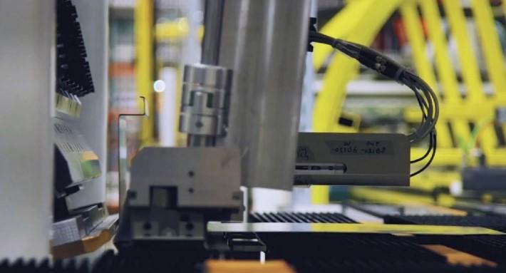
Figure 5 A WEMO swivel bender forms the edge flanges on a wrapper. Swivel benders use a bidirectional bending beam, similar to bidirectional folding machines.
After laser welding, material handling robots grasp the enclosures, place them on a final conveyor for CMT welding, automated stud welding (installing mounts for later components), and a quick grinding cycle. (The company worked with MESH Automation to create the automated stud welding, grinding, and SCADA industrial control system.) All these processes happen in sequence to ensure that about every 40 seconds—depending on the product size and thickness—a fabricated enclosure emerges from the line, ready for paint, assembly, and shipping.
Everyone knows the common narrative: Automation is taking away all the manufacturing jobs. But that wasn’t nVent HOFFMAN’s experience. The automated line launched in October 2016, and since then employment opportunities at the 1,000-plus-employee facility have only increased. Although some jobs held by those now retired won’t be coming back, the number of job openings continues to increase. But the mix of jobs has changed. The factory now employs not just press brake operators and welders, but also various levels of automation technicians.
“We’ve had to increase our level of technical knowledge at all levels,” Johnson said. “We’ve created many automation and maintenance technician positions, and the demand for their skill sets will only increase in the coming years.”
The company’s automation journey at the Anoka facility also shows the increasing level of collaboration between different industry players: laser cutting automation from Amada, robotics from ABB, bending automation from WEMO, automated laser welding integration from AWL, the laser welding power source from TRUMPF, optics from Precitec, CMT welding from Fronius, automated stud welding and grinding from MESH Automation, along with suppliers who designed the controls and interfaces between them. All must act in concert, and workers now must know how to work with them all. But the results are evident: The factory produces more product in less time than ever, and employment opportunities abound.
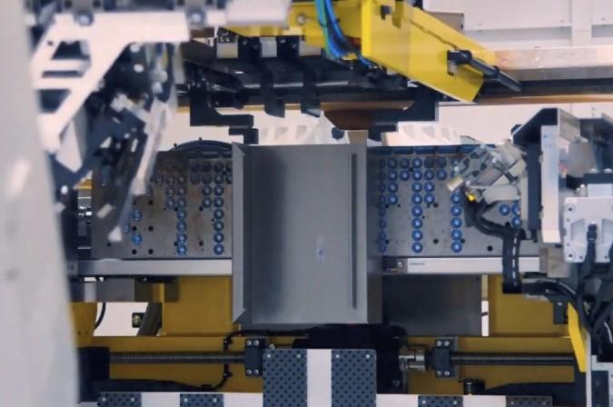
Figure 6 A robot places a wrapper component in the AWL-designed laser welding jig. After the end sheets are placed, welding commences. The U-shaped welding joint can be more than 45 in. long for the largest enclosures. But because welding is no longer a constraint, limiting the weld length isn’t an issue.


The Fabricator is North America's leading magazine for the metal forming and fabricating industry. The magazine delivers the news, technical articles, and case histories that enable fabricators to do their jobs more efficiently. The Fabricator has served the industry since 1970.
start your free subscription
Easily access valuable industry resources now with full access to the digital edition of The Fabricator.

Easily access valuable industry resources now with full access to the digital edition of The Welder.

Easily access valuable industry resources now with full access to the digital edition of The Tube and Pipe Journal.

Easily access valuable industry resources now with full access to the digital edition of The Fabricator en Español.
In this episode of The Fabricator Podcast, Caleb Chamberlain, co-founder and CEO of OSH Cut, discusses his company’s...


