


Technical Support Specialist
These wiper die inserts, designed to mount onto specific holders, help smooth out wrinkles in various tube bending applications.
A customer reaches out to you with a tube forming job involving 90-degree bends. The application entails tube with a 2-in. outside diameter (OD), a 0.065-in. wall thickness, and a 4-in. centerline radius (CLR). The customer wants 200 pieces a week for a year.
Tooling requirements are a bend die, clamp die, pressure die, mandrel, and a wiper die. No problem. It looks like all the necessary tools to bend some prototypes are in the shop and ready to go. After setting the machine program, the operator loads the tube and performs a test bend to see if the machine needs to be adjusted. The first bend comes off the machine, and it’s perfect. So the fabricator sends a few bent tube samples to the customer, who then awards the contract that is sure to lead to lucrative recurring business. All seems right with the world.
A few months go by and the same customer wants to trim material costs. This new application calls for a 2-in.-OD tube with a 0.035-in. wall thickness and 3-in. CLR. Tooling from another application is in-house, so the shop can produce prototypes right away. Operators load all the tools on the bending machine and try a test bend. The first bend comes off the machine with wrinkles inside the bend. Why? It has to do with one tooling component that’s especially critical for tube bending applications involving thin walls and tight radii: the wiper die.
Two things occur during rotary draw tube bending: The outside wall of the tube collapses and thins, and the inside of the tube compresses and wrinkles. The minimum tool requirements for rotary draw tube bending are the bend die, around which the tube is bent, and the clamp die, which holds the tube in place as it bends around the bend die.
A pressure die helps maintain constant pressure on the tube at the tangent, where the bend is occurring. This provides the reactionary force to make that bend. The length of the pressure die depends on the part’s degree of bend and the centerline radius.
The application will determine the tooling you will need. Some applications call only for a bend die, a clamp die, and a pressure die. If you have a job with a thick wall formed to a big radius, you probably won’t need a wiper die or mandrel. Other applications require a full set of tools, including a wiper die; mandrel; and (for certain machines) a collet, which helps guides the tube during the bend and the plane of bend rotation (see Figure 1).
Wiper dies help support and wipe wrinkles out of the bend’s inside radius. They also minimize out-of-round tube deformation. Wrinkles occur when the mandrel inside the tube is no longer able to provide enough counteractive force.
Wipers are always used in combination with mandrels inserted inside the tube during bending. The mandrel’s primary job is to control the shape on the outside radius of the bend. Mandrels also support the inside radius, though they offer complete support for only a limited range of applications involving specific D of bend and wall factors. The D of bend is the bend’s CLR divided by the tube OD, while the wall factor is the tube OD divided by the tube wall thickness (see Figure 2).
A wiper die is used when the mandrel no longer can provide sufficient control or support of the inside radius. Generally speaking, any thin-wall mandrel bending requires a wiper die. (Thin-wall mandrels sometimes are referred to as close-pitch mandrels, the pitch being the distance between the balls on the mandrel.) Mandrel and wiper die selection depends on the OD of the tube, the tube’s wall thickness, and bending radius.
Proper wiper die setup becomes especially critical once the application requires thinner-wall tube or tighter radii. Think again to the example that began this article. What works for a 4-in. CLR might not work for a 3-in. CLR, and the material change the customer is requesting to save money comes with tighter precision required on the tooling setup.
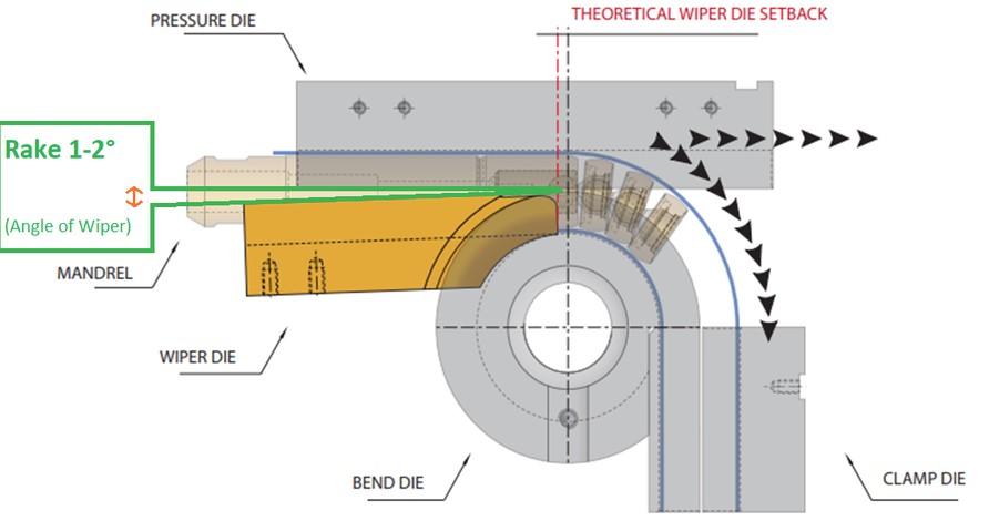
FIGURE 1 The basic components of a rotary draw tube bending setup are a clamp die, a bend die, and a pressure die. Certain setups might require a mandrel to be inserted inside the tube, and other setups call for a wiper die to be used in conjunction with the mandrel. A collet (not called here but would be positioned in the center, where you would load to the tube) helps guides the tube through the bending process. The distance between the tangent (the point where bending occurs) and the wiper die tip is called the theoretical wiper die setback.
Choosing the right wiper die; achieving proper support from the bend die, pressure die, and mandrel; as well as finding the correct wiper die position to eliminate gaps that lead to wrinkling and deformation are the key to a high-quality tight bend. As a rule, the wiper die tip setup should be offset from tangent anywhere from 0.060 to 0.300 in. (see the theoretical wiper die setback shown in Figure 1), as determined by the tube size and radius. Check with your tooling supplier to get an accurate dimension.
Make sure the wiper die tip is sitting flat with the tube groove and that there is no gap (or “hump”) between the wiper tip and the tube groove. Also check your pressure die pressure settings. If the wiper die is sitting in the right location in relation to the tube groove, add a little more pressure to the pressure die to push the tube into the bend die and help wipe out wrinkles.
Wiper dies come in various shapes and sizes. You can get rectangle/square wiper dies for rectangle and square tube applications, and you can use profile/shape wipers contoured to fit specific shapes and support unique features.
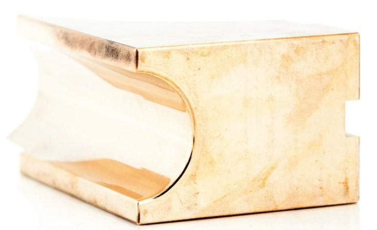
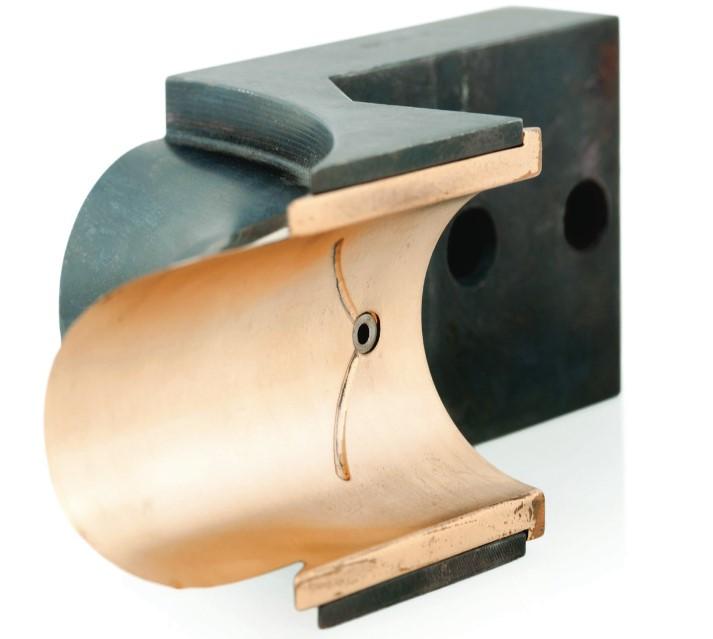
The two most common styles are the square-back solid wiper die and the wiper holder with inserts. Square-back wiper dies (see Figure 3) are used for thin-wall applications, tight D of bend (generally 1.25D or lower), aerospace work, highly cosmetic applications, and low- to medium-volume production runs.
For bends less than 2D, you can start with a square-back wiper die while you optimize the process. For instance, you can start with a square-back wiper die with a 2D bend with a 150 wall factor. On the other hand, you would likely use a wiper holder with inserts on less aggressive applications, such as a 2D bend with a 25 wall factor.
Square-back wiper dies provide maximum support of the inside radius. They also can be recut after the tip wears, but you must have an adjustment on the machine to accommodate the shorter wiper die after the recut.
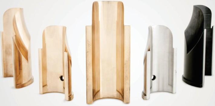
The other common style, a holder with wiper inserts, is less expensive and more cost-effective for production bending (see Figure 4). They can be used for moderate to tight Ds of bend and for bending different tube material using the same OD and CLR. Once you see the tip is worn, you can replace it. When you do, you’ll notice that the tip is automatically set at the same position as the previous insert, meaning you don’t have to adjust the wiper holder mounting. Note, however, that insert key configurations and locations on wiper die holders do vary, so you need to make sure the insert design matches the wiper holder design.
Wiper holders with inserts reduce setup time, but they aren’t recommended for tight radii. They also aren’t available for rectangle or square tube or profile shapes. Both square-back wiper dies and wiper holders with inserts can be made in a close-approach style. Close-approach wiper dies are made for minimizing tube waste, achieving a shorter working length by extending the mounting out behind the wiper and allowing the collet (the unit guiding the tube) to come closer to the bend die (see Figure 5).
The goal is to shorten the required tube length, which can save material for the right application. Although these close-approach wipers result in less waste, they offer less support than standard square-back wipers or standard wiper holders with inserts.
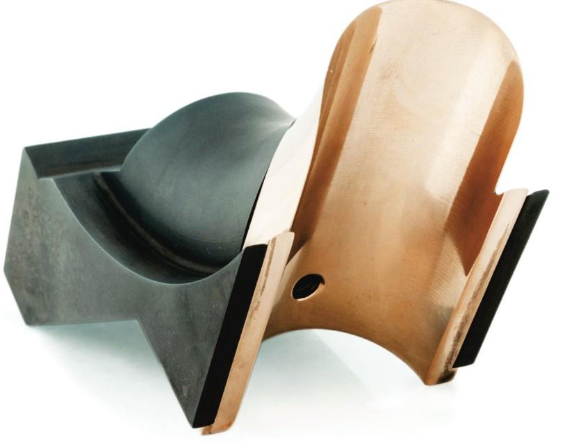
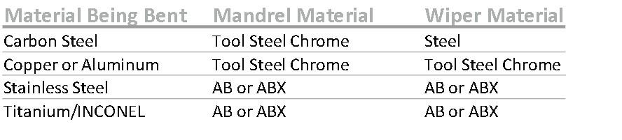
Make sure you’re using a wiper die material that’s best for the job at hand. When bending hard materials like stainless steel, titanium, and INCONEL alloys, you should use an aluminum-bronze material. When bending softer materials like mild steel, copper, and aluminum, use a wiper that’s made out of steel or chrome-plated steel (see Figure 6).

FIGURE 2 Generally speaking, less aggressive applications will not require a wiper die. To read this chart, refer to the key above.
When using a holder with inserts, the holder usually will be steel, though certain applications might require both the holder and tip to be made of aluminum-bronze.
Whether you’re using a wiper die or wiper holder with inserts, you’ll use the same machine setup for both. Secure the tube in full clamping position, then set the wiper die in from the back of the bend die and the tube. The wiper tip will set itself by tapping the back of the wiper die with a rubber mallet.
If you cannot use this method, set the wiper die or wiper holder with the insert by using your eye and a straight edge (ruler). Be careful, and use your finger or eyeball it to make sure the tip is sitting straight in line. Be sure the tip isn’t too far forward. You want to keep a smooth transition as the tube material moves past the wiper die tip. Repeat the process as necessary to accomplish an excellent-quality bend.
The rake is the angle of the wiper in relation to the pressure die. Some specialty applications in aerospace and other sectors use wipers designed to be used with little to no rake. But for most applications, the rake usually is set between 1 and 2 degrees, as shown in Figure 1, to provide enough clearance to reduce drag. You’ll need to determine the exact rake during the setup and test bending, though sometimes you can dial it in on the first bend.
Using a standard wiper die, set the wiper tip back slightly behind tangent. This leaves room for the operator to move the wiper tip forward as it wears. However, never set the wiper die tip at tangent or beyond tangent; doing so will result in a broken wiper die tip.
When bending softer material, you can apply as much rake as needed. But if you’re bending harder materials like stainless steel or titanium, try to keep the wiper die at a minimum rake. Keeping the wiper die as straight as possible with the harder materials will help wipe wrinkles out of the bend and out of the straight section behind the bend. Such a setup should also include a tight-fitting mandrel.
For the best bend quality, you should use a mandrel and wiper die to help support the inside of the bend and to control ovality. If your application calls for a wiper die and mandrel, use them both—you will not regret it.
Go back to the earlier dilemma and try to win the next contract for the thinner wall and tighter CLR. With the wiper die set in the right location, the tube comes off the machine perfect with no wrinkles. This represents the kind of quality industry wants, and quality is what industry should get.


The Fabricator is North America's leading magazine for the metal forming and fabricating industry. The magazine delivers the news, technical articles, and case histories that enable fabricators to do their jobs more efficiently. The Fabricator has served the industry since 1970.
start your free subscription
Easily access valuable industry resources now with full access to the digital edition of The Fabricator.

Easily access valuable industry resources now with full access to the digital edition of The Welder.

Easily access valuable industry resources now with full access to the digital edition of The Tube and Pipe Journal.

Easily access valuable industry resources now with full access to the digital edition of The Fabricator en Español.
In this episode of The Fabricator Podcast, Caleb Chamberlain, co-founder and CEO of OSH Cut, discusses his company’s...


