


Stamping CAE and Die Face Modeling Supervisor
The use of UHSS for automotive components has increased rapidly in recent years because of their structural performance and light weight, but their formability is constrained compared to mild steels. Getty Images
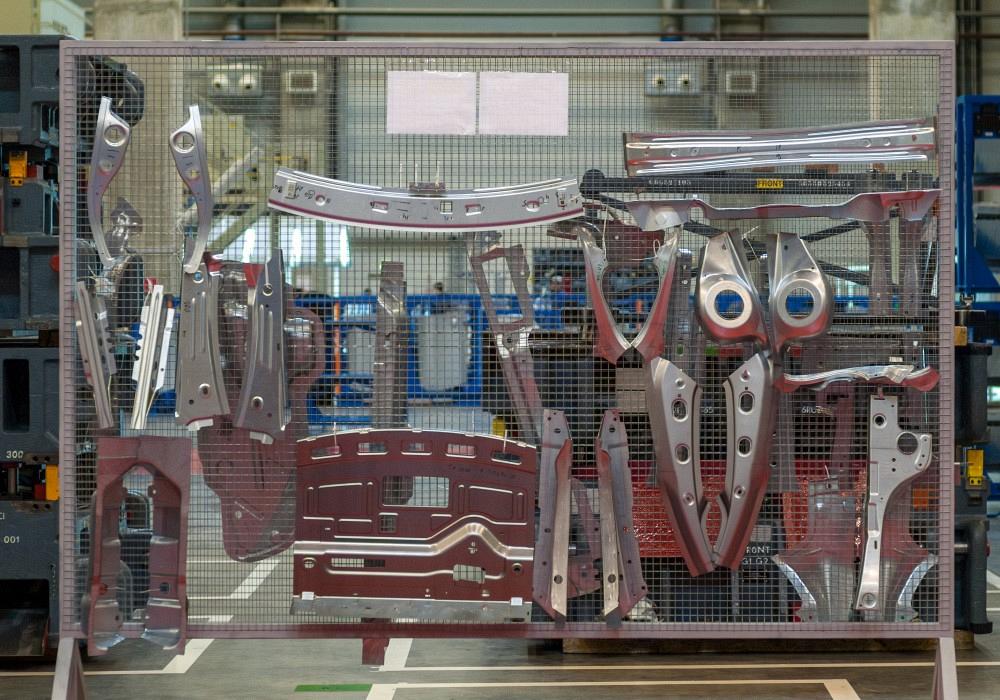
While the use of advanced and ultrahigh-strength steels (UHSS) for automotive components has increased rapidly in recent years because of their structural performance and light weight, their formability is constrained compared to mild steels. This limited formability makes it important for fabricators to understand friction and to look for ways to reduce it when simulating and designing the stamping process.
In addition, forming UHSS involves high contact pressures and high temperatures in the tool-sheet interface, and that leads to lubricant breakdown, increased galling, and tool wear.
Researchers at Oakland University recently conducted a study that analyzed how the coefficient of friction (COF) between physical vapor deposition (PVD)-coated tool steel inserts and UHSS DP1180 sheet lubricated with mill oil is influenced by lubrication thickness, sliding speed, and contact pressure.
Friction testing methods include strip pulling through a pair of flat tools imitating the die surface, strip pulling through the draw bead simulator, the twist compression test, the cup drawing test, the traditional pin-on-disc method, and Zdravkovic’s and Golovashchenko’s recently proposed methodology of dressing a sheet metal cup on a pin.
Each method has advantages and disadvantages, so the one selected should have testing conditions closest to real stamping production conditions to enable accurate numerical simulation and design methodology of the stamping process. One of the most critical factors is the contact pressure between the sheet metal blank and the die surface.
Cases with localized contact should be analyzed differently than cases with contact that takes place over large areas. The reason for this differentiation is how easily the lubrication can be forced out of the interface between the sheet and the die.
The pin-on-disc method provides a very small, local point of contact where lubrication easily escapes, allowing high-friction metal-to-metal contact. Contact pressure in this test typically can be several hundred megapascals. Zdravkovic and Golovashchenko adapted this method for sheet metal joining and local forming applications: A hemispherical sheet metal cup was formed and dressed on the pin while the flat plate was made of the die material.
Linear contacts happen where the sheet metal blank is touching, but not conforming to, the die surface. An example is a draw bead with relatively sharp radii, which the blank can just touch along the length of the draw bead.
In sheet metal drawing processes, friction forces on the flange significantly influence sheet metal inflow in the die cavity. Therefore, the contact pressures for testing in this study were selected based on existing information regarding blank holder pressure in the drawing processes. The Metal Forming Handbook suggests blank holder pressures of 2.5 MPa for deep-drawing quality steels, 1.2 to 1.5 MPa for aluminum alloys, and 2.0 to 2.4 MPa for copper alloys to suppress wrinkling.
Siebel and Beisswanger recommended an empirical formula with the required blank holder pressure proportional to the ultimate tensile strength of the formed sheet.
Based on existing information, the blank holder average pressure is 1% to 3% of the ultimate tensile strength, but this pressure is not necessarily uniformly applied to the surface of the blank. In areas where wrinkling can occur or the blank has a burr on its edge, the blank holder pressure is much greater than in relatively flat areas.
The researchers tested UHSS DP1180, selecting a geometry of the sheet-die surface interface that could prevent the edge of the blank from contacting the die surface. Even though edge contact happens in every formed blank, this configuration should be measured separately to prevent averaging the very different contact conditions that could be present in real applications in various proportions.
The 1-mm-thick DP1180 sheet metal was sheared into strips 600 mm long and 50.8 mm wide. The dimensions of the samples were selected to fit well into the horizontal hydraulic press acting as a draw bead simulator. The die surface was represented with two square inserts with rounded edges, which had a 42- by 42-mm contact area with the sheet. In this configuration, the edges of the strip were not touching the die inserts.
The inserts were fabricated from Vanadis 4 tool steel with a PVD coating, which provides a very thin layer of very high-strength and high-hardness material. The coating protects the substrate (the base tool steel material on which coating is applied) from local damage, scratching, and galling.
The strips were lubricated with mill oil 61AUS in a consistent layer along the 200- by 50.8-mm testing area. The lubrication layer’s thickness was measured in six locations on each side of the testing area using an NG2 industrial oil thickness sensor.
The lubricated strip then was clamped between two 42- by 42-mm flat surfaces using a horizontal hydraulic press mounted on a heavy-duty steel table, and also clamped to an Instron 5982 tensile testing machine (see Figure 1). In this configuration, the lower grip of the tensile testing machine was removed and replaced by the table, while the upper grip was used for pulling the strip between the clamped plates. After clamping, the strip was gripped by the upper hydraulic grip of the testing machine and pulled up 150 mm. The hydraulic grip was essential, as manual mechanical grips did not provide sufficient force to prevent the material from sliding.
The COF in this test was calculated as the pulling vertical force (Fz) applied by the tensile testing machine divided by twice the clamping force (Fx), taking into account that friction was applied on both surfaces of the strip: µ=Fz/2Fx.
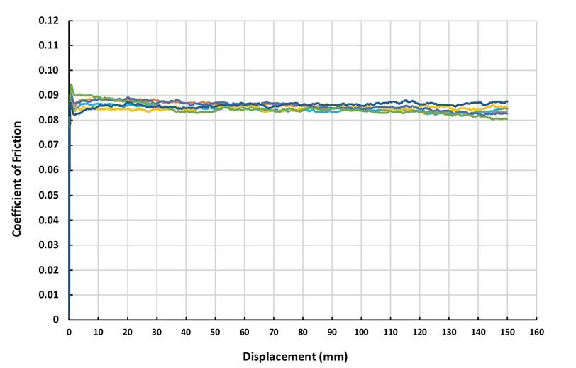
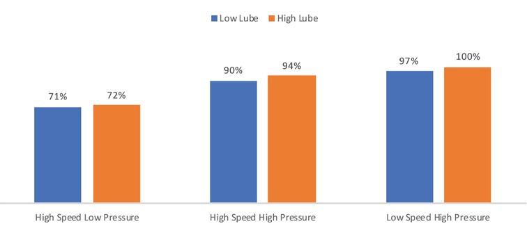
The researchers studied the effects of testing speed, average contact pressure, and lubricant layer thickness. Each of these factors was varied at two levels. Average contact pressure was applied at 11.3 and 34 MPa (19.75 and 60 kN horizontal clamping force), testing speed was 200 and 1,000 mm/min., and the lubrication layer was 60 and 110 mg/ft.2 The experimental results on COF were rather repeatable (see Figure 2).
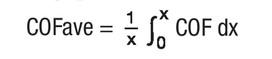
Average COF for the test was calculated by integrating the COF of each curve by displacement x and dividing the obtained integral by the total displacement of the grip X (see equation).
The result was then averaged for six tests (see Figure 3).
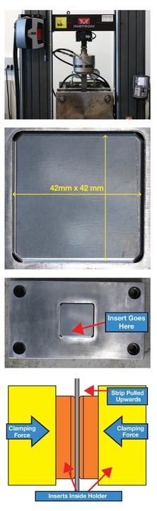
FIGURE 1. (From top) Details of the experiment: Instron 5982 with horizontal hydraulic press, testing insert, testing insert holder, and strip clamped between inserts and pulled upward in test.
The comparison of average COF within studied ranges of parameters indicated that contact pressure is the most significant factor: Increasing contact pressure by an approximate factor of three led to about a 30% increase in COF. The lubricant is getting squeezed out of the contact surface, and more metal-to-metal contact takes place. The thickness of lubrication layer was less important within the studied range of parameters: Only a few percent increase of friction was observed when the lubrication layer was reduced by nearly half. A factor of five increase of pulling speed from 200 to 1,000 mm/min. reduced COF by about 10%.
Several experiments performed with zinc-coated DP1180 steel indicated that peeling a small amount of zinc coating leads to the coating particle being dragged through the sheet and insert, greatly increasing local pressure and causing more peeling, more friction, and potential damage to the die surface.
References
T. Altan., Sheet Metal Forming Processes and Applications (Materials Park, Ohio: ASM International, 2012).
N. Reinberg, A. Mokashi, S. Nasheralahkami, Y. Demiralp, and S. Golovashchenko, “Draw bead restraining forces in sheet metal drawing operations,” STAMPING Journal, November/December 2020, p. 18-20.
Metal Forming Handbook (Göppingen, Germany: Schuler GmbH).
E. Siebel and H. Beisswanger, Deep Drawing (Munich: Carl Hanser Verlag, 1955).
S. Zdravkovic and S. Golovashchenko, “Using FEA to analyze self-piercing riveting joints in automotive applications,” STAMPING Journal, September/October 2020, p. 20-23.

Professor and Director
Oakland University Center of Advanced Manufacturing and Materials (CAMM)

PhD Candidate
Oakland University Center of Advanced Manufacturing and Materials (CAMM)


The Fabricator is North America's leading magazine for the metal forming and fabricating industry. The magazine delivers the news, technical articles, and case histories that enable fabricators to do their jobs more efficiently. The Fabricator has served the industry since 1970.
start your free subscription
Easily access valuable industry resources now with full access to the digital edition of The Fabricator.

Easily access valuable industry resources now with full access to the digital edition of The Welder.

Easily access valuable industry resources now with full access to the digital edition of The Tube and Pipe Journal.

Easily access valuable industry resources now with full access to the digital edition of The Fabricator en Español.
In this episode of The Fabricator Podcast, Caleb Chamberlain, co-founder and CEO of OSH Cut, discusses his company’s...


