


Contributing Writer

CAD expert Gerald Davis creates a multifile project for a fabricated part and changes the file names while preserving the parametric CAD links. Getty Images
Editor's Note: If you would like to download the 3D CAD files associated with this column, click here.
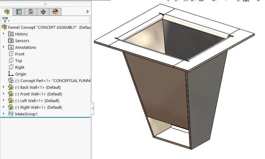
The brand of CAD that is used to produce illustrations for this column relies on the Windows operating system. If parametric CAD modeling techniques are used in a project, the file names and their folder paths become a vital part of the CAD database, also known as the design. Protecting the parametric information is part of the job. Figure 1 highlights several broken links denoted as “-?” by the software.
Avoiding such damage is easy. Don’t use Windows rename to change file names; instead, use Pack and Go, Solidworks Rename, or perhaps Save-As. Repairing such damage involves replacing broken external references with new context, essentially repeating the initial modeling process. This article is more about prevention than repair.
As a modeling scenario to demonstrate possible parametric peril, please consider Figure 2a. At this early stage of invention, the shape of the product concept is likely to change. Maybe this product will have a different flow, maybe longer or wider in some way. In this scenario, the concept piece has been given the prep-for-fabrication-but-expect-it-to-change approval.
The ideal concept model is quick and easy to shell out, but perhaps not suitable for a specific method of fabrication. We want to keep the concept model as the driver of shape so that the fabricated parts will update automatically as the design evolves.
The method of construction, welded sheet metal, is chosen for this project. Also, a given is the requirement that each piece part be assigned its own file. The drawing for the welded funnel features a bill of materials table (BOM as opposed to cut list) displaying the required piece parts.
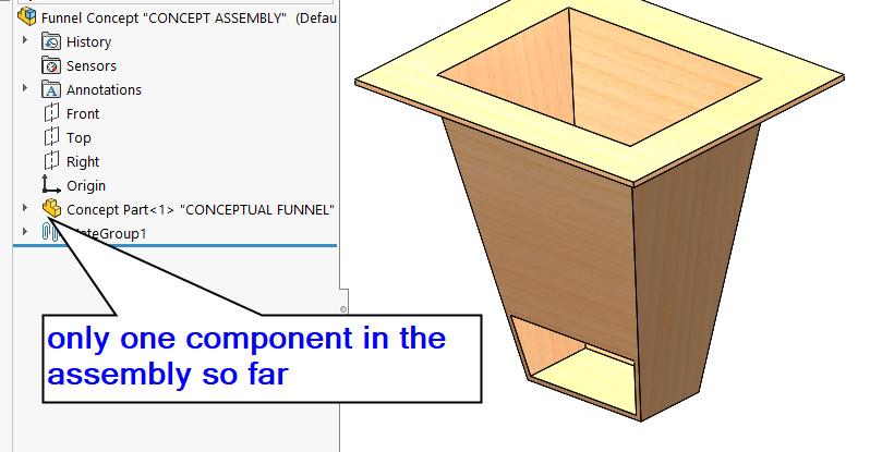
In Figure 2b, a new assembly file contains the concept part. The name of the assembly is arbitrary; design work is the priority. “Funnel Concept” works for now.
This top-level assembly is created with two goals in mind:
The parametric features (external links) emerge because of the CAD modeling technique. All of the components are created and edited within the context of the top-level assembly.
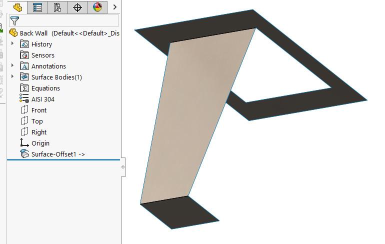
This demo walks through modeling one of the walls—more specifically, the back wall. The other three are modeled in the same manner.
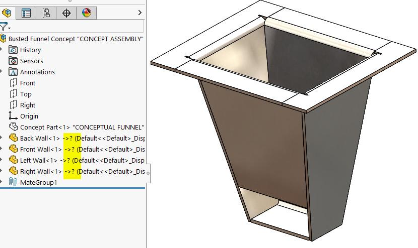
FIGURE 1A. “-?” denotes broken external references—a problem that is time- consuming to repair. Avoid this problem by using file management tools that are able to preserve the parametric links between files.
To model the back wall of the funnel, a new part is inserted into the assembly, is renamed, and saved as a part with the arbitrary file name “Back Wall.”
In a better world, we might already know the proper name to give the newly created or at least wait longer before converting virtual files to arbitrary file names. But that would be too easy. Perhaps your planning will take advantage of the ease of renaming virtual components.
CAD nuance: Newly created components are fixed in position by default. The author prefers to change them to floating and then to mate their origin to the origin of the master part in order to align all planes and axes between parent and child. You may find that “fixed” works just as well or better than mated.
Figure 3a shows the surface offset that follows the floor, back wall, and mounting flange of the concept part. As modeled, the entire top flange is a single surface. It requires trimming into an appropriate shape.
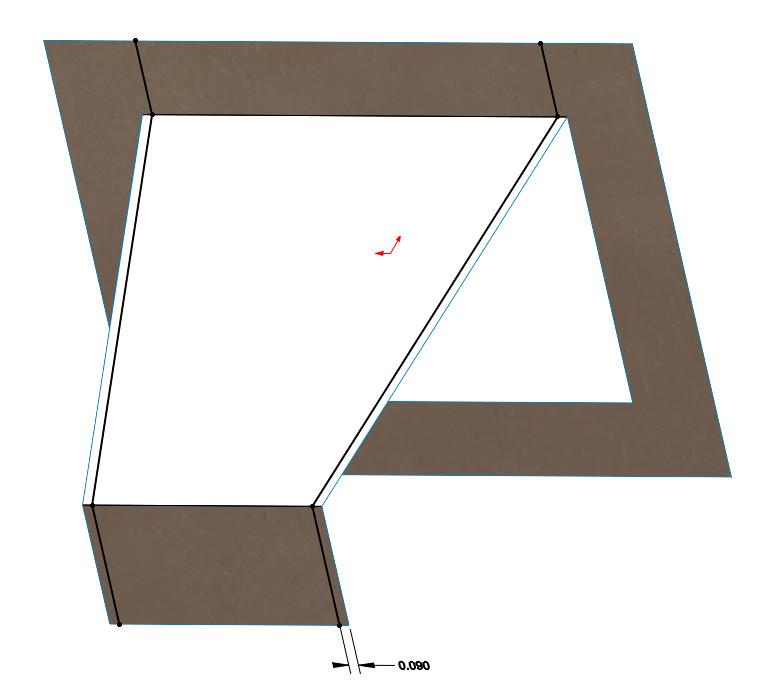
Figure 3b shows a 3D sketch that will be used for trimming. The sketch elements have parallel relations so that only a single dimension is required. This dimension could be equation-controlled to match the sheet metal thickness.
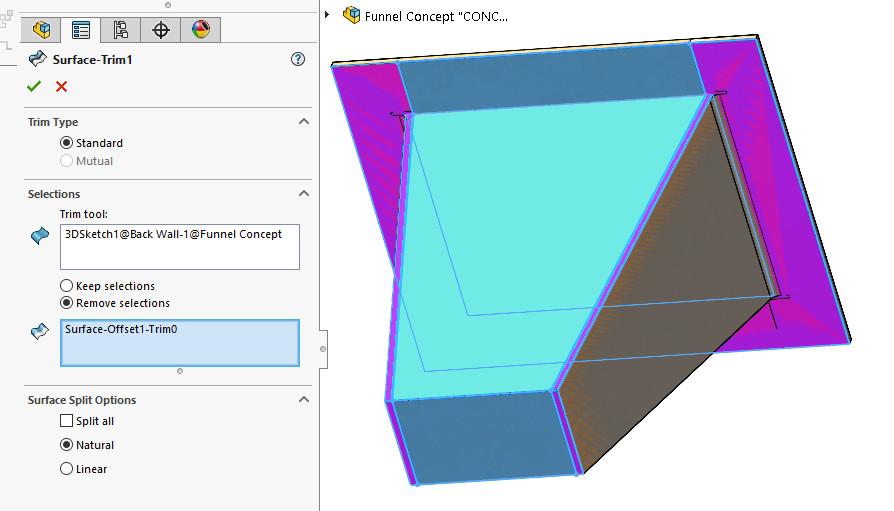
Figure 3c shows the trimming that the sketch controls. Purple goes away and cyan is kept.
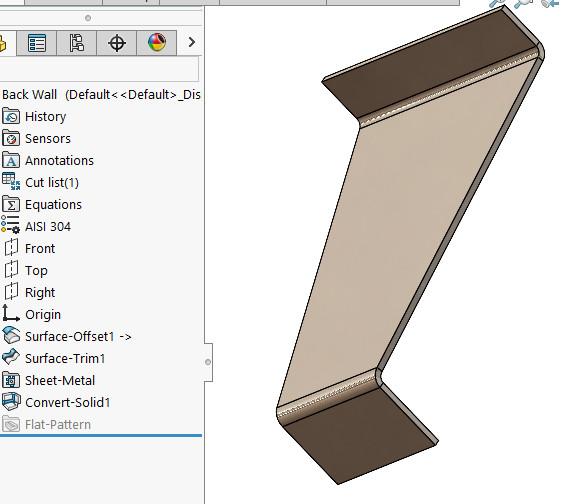
Figure 4a shows the result of converting the trimmed surface into a sheet metal body. A gauge table was used with our preferred k-factor for 13-gauge (0.090-in.) thickness.
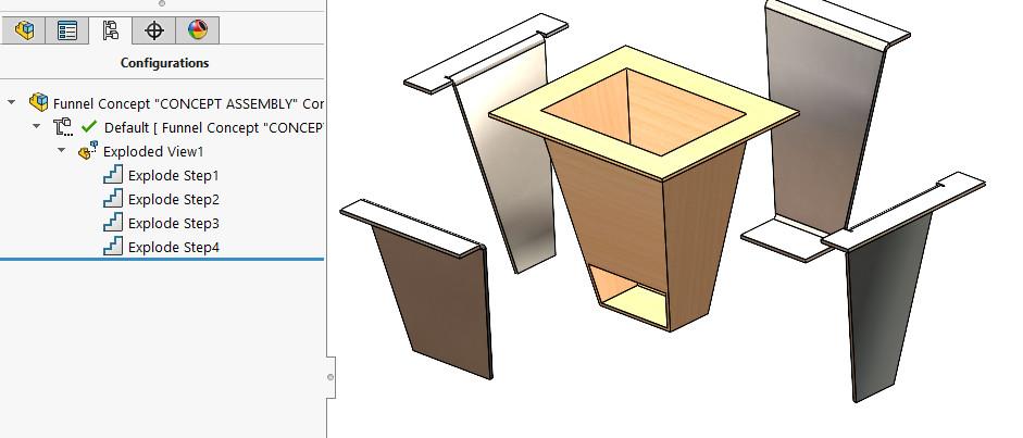
The modeling process (insert new part, edit new part with surface offset, trim, and convert to sheet metal) is repeated for the remaining walls. Figure 4b shows an exploded view of the sheet metal parts that now reside in our top-level assembly with the concept part.
Figure 5a shows the product as designed for manufacturing. The CAD files for the assembly and its components have preliminary names.
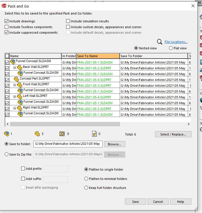
We now imagine that design review and approval have taken place. Part numbers are designated, and ideal file names are to replace the preliminary. The CAD system’s Save-As could be used with good result. However, it only works one file at a time. Save-As functionality allows us to preserve the external references, but Pack and Go is a wonderful way to change several file names all in one go.
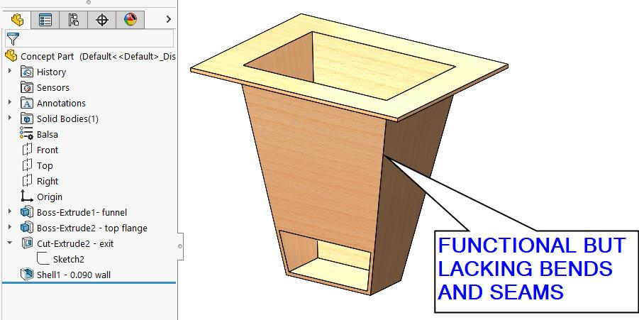
FIGURE 2A. A concept model has preliminary approval for shape and functionality; proceed with design for manufacturing. The next task is to develop sheet metal features that can be fabricated.
Figure 5b shows Pack and Go ready to Save-As our concept work with improved file names. The cells in the table accept double-click to allow editing. All of the green entries have been changed to show the ideal file names.
The save button on the Pack and Go panel launches all of the new filenames.
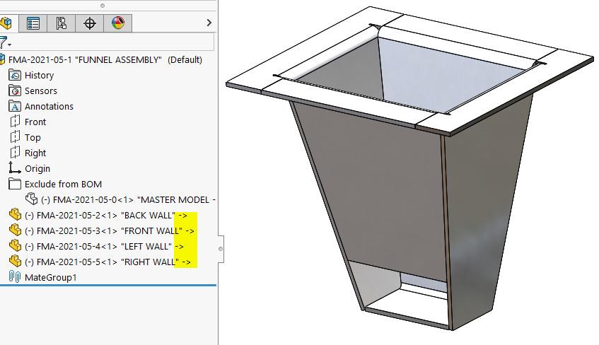
In Figure 5c, the properly named top-level assembly—now called “FMA-2021-05-1.sldasm”—shows the names of its well-mannered children. Yellow highlighting of the “->” external references (parametric links) shows our joy.
Recall the bad example—Figure 1 highlighting broken “-?” links in components. That damage was done using Windows Rename instead of Pack and Go to change the name of the top-level assembly.


The Fabricator is North America's leading magazine for the metal forming and fabricating industry. The magazine delivers the news, technical articles, and case histories that enable fabricators to do their jobs more efficiently. The Fabricator has served the industry since 1970.
start your free subscription
Easily access valuable industry resources now with full access to the digital edition of The Fabricator.

Easily access valuable industry resources now with full access to the digital edition of The Welder.

Easily access valuable industry resources now with full access to the digital edition of The Tube and Pipe Journal.

Easily access valuable industry resources now with full access to the digital edition of The Fabricator en Español.
In this episode of The Fabricator Podcast, Caleb Chamberlain, co-founder and CEO of OSH Cut, discusses his company’s...


