


Graduate Student
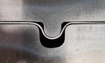
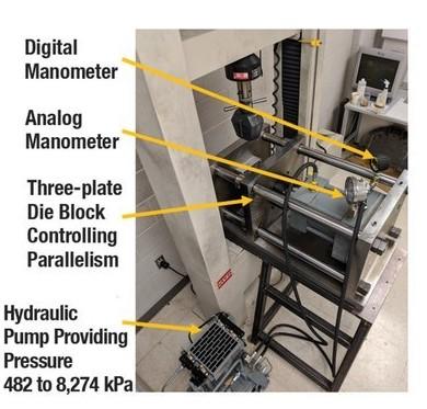
Figure 1. This experimental draw bead tool was used in the research.
In recent years automotive components increasingly have been produced from aluminum alloys and advanced and ultrahigh-strength steels for their excellent structural performance and reduced weight. However, these materials can have more constrained formability than commonly used mild steels.
When automotive stampers design sheet metal drawing processes, they must have accurate information on the distribution of restraining forces, typically provided by a series of draw beads located along the die cavity perimeter. Draw beads have become the most efficient method to provide restraining forces to draw complex-shape components from sheet material without wrinkles and splits.
The restraining forces created by draw beads are the result of bending/unbending the sheet under some level of stretching coupled with friction. The binder force needed to achieve the necessary restraining force is significantly lower when draw beads are used.
According to experimental data from H. Nine, the clamping force is about 80% to 90% of the restraining force with fixed beads. With a flat binder, when restraining force is created by friction only, the binder force needs to be five to seven times larger depending on coefficient of friction (COF). Without draw beads, a larger press size is required to provide sufficient restraining force.
Researchers at Oakland University’s Center of Advanced Manufacturing and Materials (CAMM) analyzed how restraining force can be adjusted by changing the bead penetration. The experimental work was coupled with numerical simulation to demonstrate the applicability of commercial simulation software to predict the required adjustment of the material flow in stamping dies. The experimentally measured restraining force can help determine the bead penetration required in the die design to achieve the assigned line bead restraining force in the simulation.
The draw bead simulator used in this experimental study was constructed around the idea of a sheet metal draw die: The sheet metal flows in between the male and female portions of the draw bead with some clearance, allowing sheet metal to flow outside the bead area (see Figure 1). For this study, the radii on both male and female beads were 4 mm; widths were 9 mm and 13 mm, respectively. The clearance was adjusted by the equalizer blocks, which included a set of calibrated shims separating the flanges of the tool. The hydraulic cylinder held the portions of the simulator clamped to each other. The draw bead simulator was built on a rigid die shoe system (see Figure 2). Clamping force was 34.2 kN.
The researchers used the following experimental procedure:
Using the simulation software, the researchers developed a numerical model of sheet material flow through the draw bead. A comparison of numerical and experimental results showed that the simulation model, when calibrated, could be used to direct the tryout process of connecting draw bead geometry with splitting, wrinkling, and springback.
Material deformation in the draw beads was simulated in two steps:
In the model, after the strip was formed by the draw bead in step 1, the same draw bead moved horizontally to the left in step 2 while the sheet was restricted from one side. The results of in-plane force were used to evaluate the corresponding restraining force on the constrained side of the strip.
The experimental study was carried out with an adjustable draw bead insert; the advancement of the male bead and the clearance between the flanges of the male and female portions of the tool could be independently changed. The male bead was fabricated as a separate insert with position adjusted by the first set of shims; the gap between the flanges of the draw bead inserts was adjusted by the second set of shims acting with equalizer blocks.
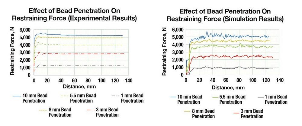
The results on draw bead restraining force for different male bead penetrations and 0.99-mm clearance between the flanges of the male and female beads (leaving 10% clearance of sheet metal thickness between the sheet and the inserts) showed that the restraining force can be varied by approximately a factor of four. This gives the die designer plenty of flexibility to perform a virtual tryout and achieve the desired distribution of restraining forces around the perimeter of the blank by selecting corresponding bead penetration. The material might not fully conform to the shape of the beads at smaller bead penetrations, and the wrapping angle where friction contributes to the restraining force varies significantly with the depth of bead penetration; therefore, an analysis is required for each bead geometry.
The numerical simulation with the software was targeted to define the COF that correlates the numerical restraining force to its experimental value. Results indicated that 0.14 provides the best correlation for all depths of penetration. Figure 3 shows the experimental and simulation results with different bead penetrations from 1 mm to 10 mm.
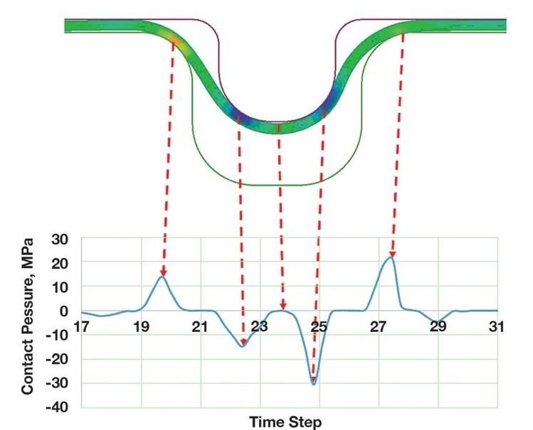
Contact pressure varied in different locations of the draw bead surface. The positive and negative peaks shown in Figure 4 indicate whether the pressure is applied to the female bead or the male bead. Pressure distribution depends on bead geometry and therefore is not uniform.
The experimental study and numerical simulations indicated that draw bead restraining force can be varied significantly by adjusting the bead penetration. Results demonstrated that numerical simulation can be successfully used to design the distribution of restraining forces if the COF is selected based on correlation with experimental data.
A simple set of tests performed with the draw bead tool can serve as a transition between the line bead simulation selecting the necessary restraining force and the design of the die.
These experimental and numerical studies illustrate a simple way to define the COF for small-radii areas of a stamping die with significant friction.
ReferenceH. Nine, “Draw bead forces in sheet metal forming,” in proceedings of Mechanics of Sheet Metal Forming international symposium, 1978, pp. 179-209.

Professor and Director
Oakland University Center of Advanced Manufacturing and Materials (CAMM)

PhD Candidate
Oakland University Center of Advanced Manufacturing and Materials (CAMM)


The Fabricator is North America's leading magazine for the metal forming and fabricating industry. The magazine delivers the news, technical articles, and case histories that enable fabricators to do their jobs more efficiently. The Fabricator has served the industry since 1970.
start your free subscription
Easily access valuable industry resources now with full access to the digital edition of The Fabricator.

Easily access valuable industry resources now with full access to the digital edition of The Welder.

Easily access valuable industry resources now with full access to the digital edition of The Tube and Pipe Journal.

Easily access valuable industry resources now with full access to the digital edition of The Fabricator en Español.
In this episode of The Fabricator Podcast, Caleb Chamberlain, co-founder and CEO of OSH Cut, discusses his company’s...


