


Is a press brake job with side gauging giving you trouble?
From factory-built gauging systems to press brake toolmakers to a customized homemade one, there are options

Getty Images
Question: I read your column every chance I get, but sadly I do not get to read enough of them. Management generally keeps them in the front office, but now and then one escapes to the shop floor.
I have a question about side gauging for bends that are not perpendicular to the part edge (see Figure 1). I set my gauge angle from the face of the die for the bend angle required on the print. But it never works out as planned when I have a bend already in the part that contacts the side gauge. I’m always going back after the first test piece and adjusting the gauge angle. It is never consistent. The workpiece always rocks a bit against the gauge, and sometimes the rocking can get bad. The gauge angle can be a little more or less in different amounts, even within the same run of parts. Why is this happening, and what can I do to stop all the inconsistencies?
Answer: It sounds like you have two problems—one related to the press brake and another being that people on the shop floor aren’t reading The FABRICATOR magazine. You might want to speak with managers and explain the value of circulating the magazine on the shop floor. You can also review articles on your own time at thefabricator.com as well as my website, theartofpressbrake.com.
Now to your question about side gauging. This problem is more complicated than you might think. We’ll start with what’s causing your problems, and then we’ll look at how to work around them.
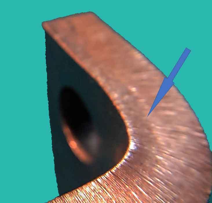
Take a formed part—the thicker the better—and look at the part edge right at the bend. Do you notice a small amount of material bulging into a convex shape anywhere from halfway through the material thickness or less? If so, the remainder of the thickness should pull inward in a concave shape (see Figure 2).
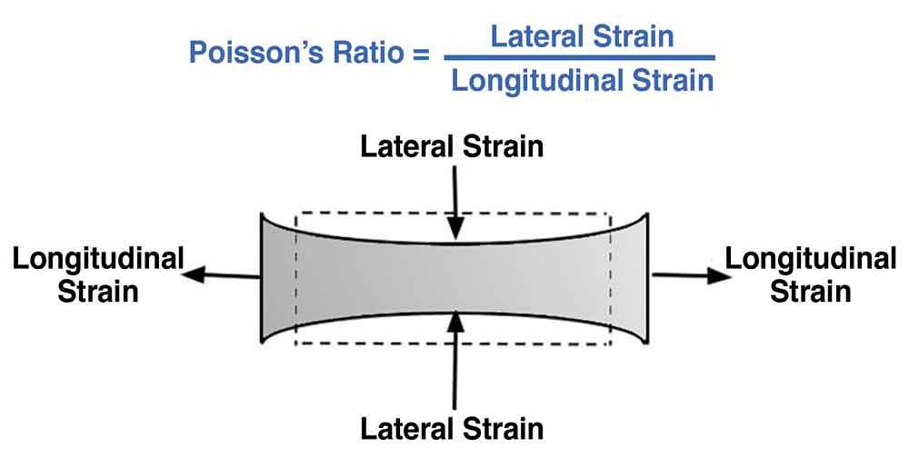
This lengthening and subsequent narrowing shows Poisson’s ratio at work. Put in simple terms, Poisson’s ratio describes how lengthening in one axis is accompanied by narrowing in the other axis (see Figure 3). Your parts are stretching and shrinking at the point of bend. If you slide the convexed edge of a previously formed bend against the side gauge, the part will rock on the side gauge and create wide variation in your bend angles.
Expansion and Compression
When you bend sheet metal on the press brake, the material expands on the outside (tensile stress) and compresses on the inside (compressive stress). Between these two opposing forces lies the neutral axis, a theoretical line which goes through no physical change. The neutral axis starts at 50% of the material thickness while the material is flat, then moves during forming toward the inside surface of the bend. The neutral axis moves toward the inside surface because the material is being compressed during bending.
Note that the relocation of the neutral axis after forming is predictable using the k-factor, allowing you to calculate an accurate bend allowance and bend deduction. It is also possible to mathematically calculate a neutral axis location greater than 50%, especially in radius and profound radius bends. If that is the case, the neutral axis location is pulled back to 50% for the remaining calculations. The reason for this is simple: Compression cannot exceed expansion. For more detail on this, visit thefabricator.com and search for “Analyzing the k-factor in sheet metal bending.”
What Does This Mean for You?
You’ll probably notice that your gauge angle works when no previous flange is involved. But if you have a second bend, you’ll notice that rocking as the convex and concave surfaces of that previous bend interact with the side gauge. The compression forces bulging on the material’s edge, while the expansion on the outside of the neutral axis draws inward. Slide that bulged edge of a previous bend against the side gauge and your part rocks against it. That’s your gauging problem.
This bulging happens with all metal bending, regardless of thickness, though it becomes more pronounced in thicker sheet and plate. The intensity varies with the metal’s grain direction as well. Bending perpendicular to (against) the grain tends to lessen the effect, while bending longitudinal to (with) the grain compounds the bulging (or “convexing”), making your gauging problem worse and even less consistent.

Figure 1
The part rocks against the side gauge during the second bend in the sequence, resulting in significant inconsistencies.
Correcting the Process
How do you deal with this in day-to-day gauging operations? Knowing what is causing your gauging issue is a large part of finding the solution. Sometimes you can simply change the forming order and perform the bends that require a side gauge first. Of course, this is not always the best, easiest, or most practical way to accomplish a series of bends. Not to worry; you have options.
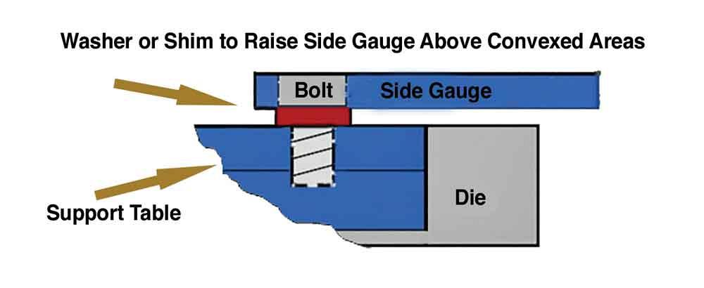
If your material is thicker—let’s say ¼ in., such as the material shown in Figure 1—you simply need to raise the side-gauge arm to a height of half a material thickness or more. For instance, as shown in Figure 4, you can use a washer or shim to raise the gauge so that it contacts the plate edge above the bulged area in the previous bend.
Of course, this option will not work perfectly as the bulged, convex area of the bend can still hang up on the side gauge, causing you to either lose the bend-line angle as the part location shifts or force the stop to move, causing the next bend-line angle to be off.
A preferred option is to modify the side gauge bar itself. You can do this in one of two ways, the first being to alter the gauge arm. Grind or cut an area away at the point on the gauge arm where the convex area will make contact. Doing so will stop any rocking of the part on the side gauge and, in turn, will either stop or dramatically reduce any bend-line angle error.
If you form a lot of bends that require a side gauge—be it perpendicular to the bend or at another angle—you might consider taking the time to build a side gauge with built-in reliefs. Depending on your needs, these could have multiple points or flats.
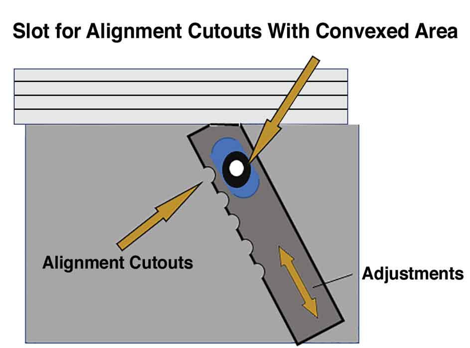
The side gauge bar in Figure 5 has a short slot that allows adjustments in the side gauge, so you can contact the needed location to accommodate the convex portion of the previously bent edge. This is simple to build even if you’re not a machinist.
Many Ways to Side-gauge
You have plenty of side-gauging options, from sweet factory-built gauging systems from one of the press brake toolmakers to homemade ones. All should work fine, but you still might need a little customizing to get the job done consistently. Once you get it right, you should be able to build better parts, have quicker setups, and enjoy shorter run times.
About the Author

About the Publication

subscribe now

The Fabricator is North America's leading magazine for the metal forming and fabricating industry. The magazine delivers the news, technical articles, and case histories that enable fabricators to do their jobs more efficiently. The Fabricator has served the industry since 1970.
start your free subscription- Stay connected from anywhere

Easily access valuable industry resources now with full access to the digital edition of The Fabricator.

Easily access valuable industry resources now with full access to the digital edition of The Welder.

Easily access valuable industry resources now with full access to the digital edition of The Tube and Pipe Journal.

Easily access valuable industry resources now with full access to the digital edition of The Fabricator en Español.
- Podcasting

In this episode of The Fabricator Podcast, Caleb Chamberlain, co-founder and CEO of OSH Cut, discusses his company’s...


