


Technical Support Specialist

A longstanding problem in tube bender tooling setup is tooling misalignment, which leads to scrapped tube (wasted material) and requires additional setup time to align the tooling (wasted time). Getty Images
Tube and pipe bending applications have been growing more complex over the decades, often driven by increasingly sophisticated demands by OEMs and facilitated by advances in bending machines, tooling, and software. One longstanding problem is tooling misalignment. Unacceptable marking and galling of material often occur during bending when the tube or pipe is pulled through misaligned rotary draw tools. This results in scrap losses and lost time when the machine operator has to stop bending and put more effort into getting the tooling aligned. Nobody wants to scrap tubing or waste time on lengthy setups, but the stakes are especially high when the application uses expensive tubing or involves high-volume production. Tube is money and time is money; losses add up from every scrapped tube and every minute of downtime.
One solution is to use interlock tooling (see Figure 1). As the name implies, interlock tooling integrates the wiper die, clamp die, and pressure die, fitting them inside the bend die’s interlock opening. Once used mainly in aerospace, cosmetic, and high-volume applications, interlock tooling has become a preferred tooling design for nearly any tube bending application because it provides high-quality bends and facilitates easier setups.
The interlock option also works well with stacked tooling. When designed for a stack rather than for a single-tool installation, the tools have a higher aspect ratio, and they have a greater tendency to deflect or move under pressure. The interlock design helps stacked tooling stay aligned through the bending process, resulting in less deflection and movement.
Although interlock tooling costs about 9% to 12% more than standard tools, it can offer significant value in reduced scrap and setup time. Bear in mind that the machine must be rigid and sturdy to take advantage of everything that interlock tooling has to offer. A machine worn and stressed from decades of use isn’t as likely as a new machine to provide the necessary stability.
Like interlock tooling, the mandrel—the tool that fits into the tube or pipe’s ID—also facilitates quality bends. The primary function of the mandrel, for any tooling style, is to prevent the OD from collapsing.
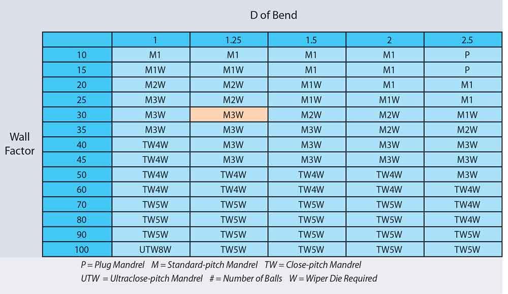
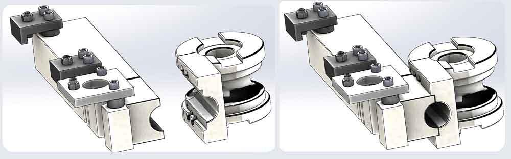
Mandrel Types. Several types are available. Many use a series of linked balls (in some cases, just one ball) to support the tube or pipe beyond tangent as it bends (see Figure 2). To determine which mandrel is best for bending your parts, you can use the following formula:
• Wall Factor = OD divided by wall thickness
• D of Bend = Centerline radius divided by OD
Use the wall factor and D of bend to determine how many balls you need for the mandrel. For example, if the OD is 2 inches, the wall thickness is 0.065 in., and the bend’s centerline radius is 2.5 in., then:
• Wall Factor = 2 ÷ 0.065 = 30.769
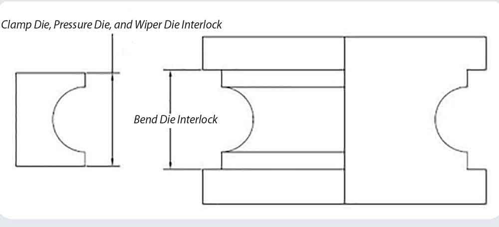
Figure 1
The bend die interlock is a machined cavity that keeps the other tools aligned despite the substantial forces that can disrupt the tooling alignment.
• D = 2.5 ÷ 2 = 1.25
Using a table provided by a machine or a tooling manufacturer (see Figure 3), find the row that has the closest wall factor and the column with the D of bend. In this case, the intersection of 30 wall factor and 1.25 D of bend shows an abbreviation, M3W, which indicates a standard-pitch mandrel with three balls. The suffix W indicates that a wiper die is necessary. Bear in mind that these tables are guides, and some deviations can be beneficial. For example, adding a ball usually improves the bend quality; the tradeoff is an increase in friction.
An application that has a low wall factor uses a plug-style or one-ball mandrel. As the wall factor increases, the number of balls required increases, and can lead to using a thin-wall or ultrathin-wall mandrel.
Using a spreadsheet simplifies matters, allowing you to enter various combinations of numbers to find the mandrel types needed for a variety of bends.
Mandrel Alloys. For a mandrel to work well, it needs to move smoothly through the ID. Friction causes galling, a buildup of material on the mandrel’s surface, which leads to more friction and more galling.
For bending hard materials such as stainless steels, titanium alloys, and workpieces made from INCONEL® alloy, most mandrel vendors use an aluminum bronze alloy. For bending relatively soft materials such as mild steel, aluminum, and copper, most specify a steel mandrel with chrome plating. Many coatings are available to help with lubricity.
Regardless of the tools you use, and no matter what substrate they’re made of, a lubricant is necessary to limit wear and extend the tooling life cycle.
Although a tooling set isn’t as expensive as a capital item—it’s a consumable item—it’s still pricey, so it’s in your interest to make it last as long as possible. The tool set’s service life is based on the base material, bending difficulty, lubrication effectiveness, machine condition, and tube cleanness.
Just as tooling substrates vary by application, so does the lubricant. As with mandrel alloys, the various lubricants correspond to the material’s hardness, the heat and pressure that develop during bending, and a few other factors. Lubricant suppliers and most tooling manufacturers can provide recommendations on lubricant selection.
Another key factor in getting the longest possible service life from the tool set is tooling care. A setup for new tooling on a new machine isn’t the same as a setup after the tooling and machine have experienced some wear. A little finesse in updating the setup goes a long way in maintaining quality bends, but often the setup technician or the machine operator isn’t aware that slight changes are in order. Many compensate by simply increasing the pressure. This can maintain the bend’s appearance, but it’s a short-term solution with long-term consequences. It accelerates the wear and tear on the machine and the tooling, which means the operator needs still more pressure to accomplish good bends. This is no way to use an expensive consumable or a capital investment, but a little education on best practices for tooling setup can help everyone contribute to extending tooling life.
Paul McGowan is a technical support specialist for Omni-X USA Inc., 2751 W. Mansfield Ave., Englewood, CO 80110, 800-275-6664, pmcgowan@omni-x.com, www.omnibend.com.

The Tube and Pipe Journal became the first magazine dedicated to serving the metal tube and pipe industry in 1990. Today, it remains the only North American publication devoted to this industry, and it has become the most trusted source of information for tube and pipe professionals.
start your free subscription
Easily access valuable industry resources now with full access to the digital edition of The Fabricator.

Easily access valuable industry resources now with full access to the digital edition of The Welder.

Easily access valuable industry resources now with full access to the digital edition of The Tube and Pipe Journal.

Easily access valuable industry resources now with full access to the digital edition of The Fabricator en Español.
In this episode of The Fabricator Podcast, Caleb Chamberlain, co-founder and CEO of OSH Cut, discusses his company’s...


