
Spitfire & GT6 Forum
75 wiring from scratch - first of many
Posted by chrisrintz


 |
Topic Creator (OP)
Oct 18, 2018 05:18 PM
Joined 14 years ago
231 Posts
|
I have begun the rewiring of my 75 Spitfire from scratch. Purchased the complete kit from Advance Auto Wire, which looks to be a great improvement. The PO wired up the car in a manner that ensured all the basics worked, and he clearly had a far greater understanding of automotive wiring than I could ever hope to possess, Pretty much nothing of the original installation resembled any wiring diagram I have come across, so i have no basis of comparison. I am fairly good with the mechanical stuff, but I have been more of a connect the dots electrician. Feeling a bit overwhelmed and confused so here's my initial questions...
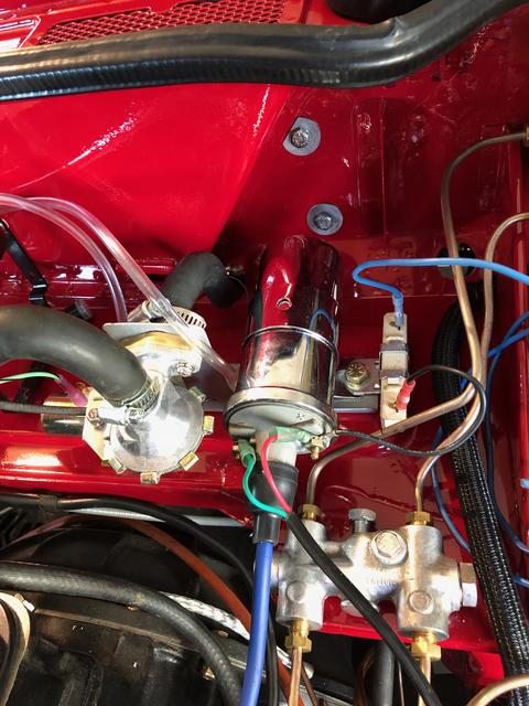
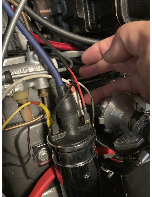
1. See attached photo. I installed a Pertronix distributor and coil before I embarked on the frame off, and rewired it exactly as it was when it last ran. Still missing lead to the tack, but fundamentally 2 wires from the dizzy, and a black wire to the ceramic resistor, blue wire neatly coiled up and connected to nothing. Most diagrams seem to show this blue wire (or WY) running back to the starter solenoid. Trying to figure out how this ever started and ran decently previously, but I want to do it correctly this time...thoughts?
2. I previously replaced the Lucas with an AC Delco alternator. PO had small brown sense wire connected to battery lug on solenoid which I reconnected as original...Advance indicates the sense wire simply connected to the battery lug on the alternator itself...any issues with this?
3. My front side market lights have a single red wire...no grounding black ire or tab to connect to. the rears have the more typical black and red pigtail. Are the front lights grounded though the socket somehow to the body through the bolts or somehow internally. These clearly never had a two wire pigtail or the little tag that most of the other lights include.
There is a lot of magic that goes on in my new load center (7 relays, 8 fuses), which I will trust, but this ignition wiring has me baffled. Thats in advance for any help provided!!
Attachments:
IMG_2375.jpg 61 KB

spitfire50
Paul Mugford
|
Oct 18, 2018 06:09 PM
Top Contributor
Joined 13 years ago
19,839 Posts
|
Chris,
You've missed a wire somewhere. The way you have it now there is no connection to the battery positive terminal.
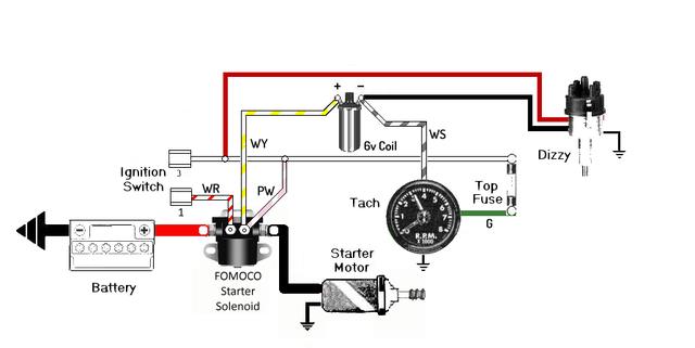
There should be a wire from the ignition switch to the ceramic ballast resistor. That end of the resistor should be connected to the red wire of the Pertronix. The positive side of the coil should connect to the other end of the ballast resistor, and to the starter solenoid. The solenoid terminal is one that is only live when the engine is being cranked.
The coil negative gets the Pertronix black wire and a tach wire.
All the best,
Paul
TRF# 10423
You've missed a wire somewhere. The way you have it now there is no connection to the battery positive terminal.
There should be a wire from the ignition switch to the ceramic ballast resistor. That end of the resistor should be connected to the red wire of the Pertronix. The positive side of the coil should connect to the other end of the ballast resistor, and to the starter solenoid. The solenoid terminal is one that is only live when the engine is being cranked.
The coil negative gets the Pertronix black wire and a tach wire.
All the best,
Paul
TRF# 10423

Doug in Vegas
Douglas D
|
Oct 18, 2018 07:34 PM
Top Contributor
Joined 8 years ago
14,775 Posts
|
|
|
Topic Creator (OP)
Oct 18, 2018 08:50 PM
Joined 14 years ago
231 Posts
|
In reply to # 1572440 by Doug in Vegas
You are powering the unit off the coil but the coil is only getting 6v.
Tap the red wire to the other side of the resistor.
Tap the red wire to the other side of the resistor.
Thanks - So basically lose the blue wire to nowhere completely and replace it with the red wire from the coil. The black wire from the resistor stays as is, to the + terminal of the coil. Correct? Sorry I am still a bit
|
|
Topic Creator (OP)
Oct 18, 2018 08:54 PM
Joined 14 years ago
231 Posts
|
In reply to # 1572422 by spitfire50
Chris,
You've missed a wire somewhere. The way you have it now there is no connection to the battery positive terminal.
There should be a wire from the ignition switch to the ceramic ballast resistor. That end of the resistor should be connected to the red wire of the Pertronix. The positive side of the coil should connect to the other end of the ballast resistor, and to the starter solenoid. The solenoid terminal is one that is only live when the engine is being cranked.
The coil negative gets the Pertronix black wire and a tach wire.
All the best,
Paul
Thanks Paul - so many wires....

|
Doug in Vegas
Douglas D
|
Oct 18, 2018 11:20 PM
Top Contributor
Joined 8 years ago
14,775 Posts
|
In reply to # 1572456 by chrisrintz
Thanks - So basically lose the blue wire to nowhere completely and replace it with the red wire from the coil. The black wire from the resistor stays as is, to the + terminal of the coil. Correct? Sorry I am still a bit
In reply to # 1572440 by Doug in Vegas
You are powering the unit off the coil but the coil is only getting 6v.
Tap the red wire to the other side of the resistor.
Tap the red wire to the other side of the resistor.
Thanks - So basically lose the blue wire to nowhere completely and replace it with the red wire from the coil. The black wire from the resistor stays as is, to the + terminal of the coil. Correct? Sorry I am still a bit
Advance uses Lucas colors for the most part so in the diagram above your resistor is the pink wire. Hook a white wire to the top of the resistor in the picture along with the red wire from the distributor. The black wire from the distributor goes to the - side of the coil. The + side of the coil hooks to the lower end of the resistor so that's fine in the picture.
The only other thing you will hook up is the signal wire for the tachometer and it's to the - side of the coil.
|
|
Topic Creator (OP)
Oct 18, 2018 11:27 PM
Joined 14 years ago
231 Posts
|
|
|
Topic Creator (OP)
Oct 19, 2018 03:40 PM
Joined 14 years ago
231 Posts
|
|
Doug in Vegas
Douglas D
|
Oct 19, 2018 04:16 PM
Top Contributor
Joined 8 years ago
14,775 Posts
|
In reply to # 1572587 by chrisrintz
Any thoughts on the alternator or lights?
I went to their website and didn't see anything for the Spitfire.
Did you get a booklet with it?
You should have a page with color codes.
Here's the Lucas color codes:
https://www.mgexp.com/article/lucas-colours.html
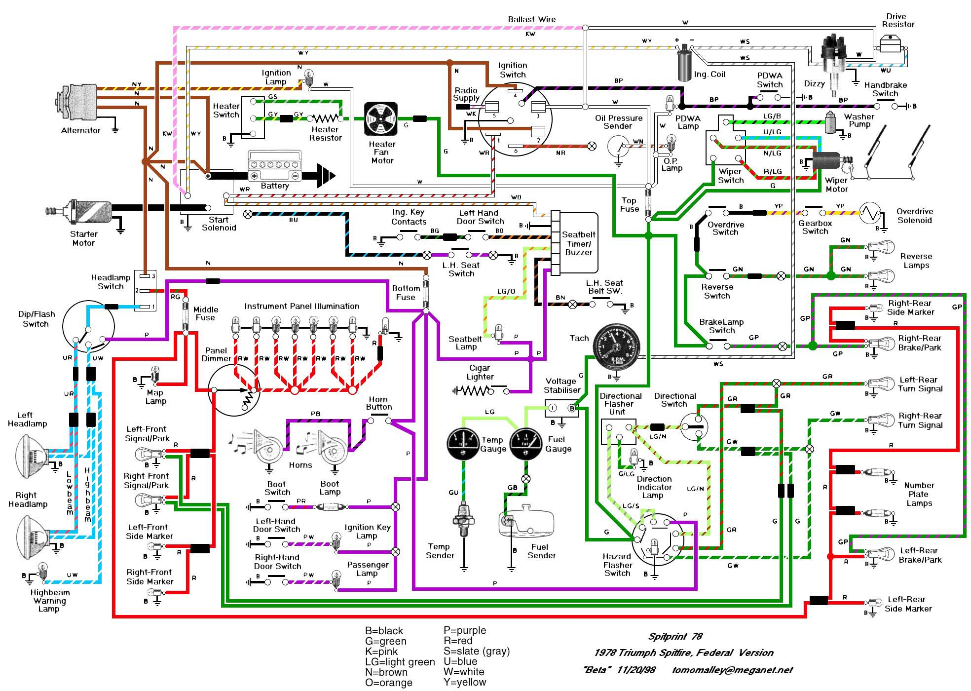
And the schematic for the 78-80.
Running wire and making connections is best done with just enough beer to where you have a moment of doubt and think that you have to rip it all out and start over but not enough to actually do it.
|
Doug in Vegas
Douglas D
|
Oct 19, 2018 09:28 PM
Top Contributor
Joined 8 years ago
14,775 Posts
|
I have a few basic questions specific to the wiring harness you bought and have a personal interest as I may do something similar.
BTW: Two pictures of your engine compartment looking down at a 45° angle from each side and I guarantee you everyone will dive in telling you what you need to improve reliability and performance. Every new project is exciting here.
We have road and track here and a few EVs.
BTW: Two pictures of your engine compartment looking down at a 45° angle from each side and I guarantee you everyone will dive in telling you what you need to improve reliability and performance. Every new project is exciting here.
We have road and track here and a few EVs.
 Walla Walla, WA, USA
Sign in to contact
1969 Triumph Spitfire "Walla Walla"
1969 Triumph Spitfire "Portland" 1972 Triumph Spitfire MkIV "Spokane" 1975 Triumph Spitfire 1500 "Dayton" & more |
Oct 19, 2018 10:16 PM
Top Contributor
Joined 12 years ago
14,827 Posts
|
Quote:
2. I previously replaced the Lucas with an AC Delco alternator. PO had small brown sense wire connected to battery lug on solenoid which I reconnected as original...Advance indicates the sense wire simply connected to the battery lug on the alternator itself...any issues with this?
3. My front side market lights have a single red wire...no grounding black ire or tab to connect to. the rears have the more typical black and red pigtail. Are the front lights grounded though the socket somehow to the body through the bolts or somehow internally. These clearly never had a two wire pigtail or the little tag that most of the other lights include.
3. My front side market lights have a single red wire...no grounding black ire or tab to connect to. the rears have the more typical black and red pigtail. Are the front lights grounded though the socket somehow to the body through the bolts or somehow internally. These clearly never had a two wire pigtail or the little tag that most of the other lights include.
2. Is the alternator a single wire or a three wire? On the three wire, the standard diagram for them shows the idiot light connected to one of the two wires in the two wire plug and not the main pole. I assume the idiot light is connected to the single pole unless they were not used with the single pole alternators (used a gauge instead?)
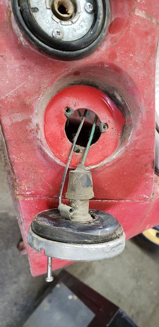
3. On the side markers I have worked on for the MkIV and 1500 there was a ground clip on the bulb socket. One of those little brass clips as shown in the photo on the side of the light socket. The cannot ground through the bonnet as there is no direct solid connection to ground. The grounds should run with the hot leads back to the center of the bonnet then back along the frame where they ground at various places on the frame, depending on the year.
da
Dan Aycock
Walla Walla, Wa.
Yellowhawk Valley Spitfires
69, 69, 72, 75, 78, 79 Spitfires
TRF# 006047
Attachments:
20181005_104933.jpg 36 KB

trrdster
Wayne Tate
Spencer, NC, USA
Sign in to contact
1949 Triumph 2000 Roadster
1970 Triumph TR6 1978 Triumph GT6 "Scooter" 1978 Triumph Spitfire "Scooter" & more |
Oct 20, 2018 06:41 AM
Top Contributor
Joined 8 years ago
4,916 Posts
|
Christopher, You will get the wiring with help from our friends. A good choice to add the new circuits and relays.
I know you don't need the grief, but you also will need to address the PDWA valve, that bolt indicates a issue internally.
Do a search, lots of different approaches.
Sorry if you have already been checking into it..
Wayne
1970 TR6
2000 Jaguar XK8
1949 Triumph Roadster 2000
1978 Spit6 (getting all the good GT6 parts, all poly suspension and Spax shocks)

gcelenta
George Celentano
|
Oct 20, 2018 07:32 AM
Joined 9 years ago
190 Posts
|
Hey Chris I'm not sure if you got everything sorted out already with the help of the guys above, but I also installed the Advance Auto Wire Harness with Petronix ignition, coil (12 volt), and a Denso alternator. Let me know if you have any questions.
Regards,
George
Regards,
George
|
|
Topic Creator (OP)
Oct 20, 2018 10:25 AM
Joined 14 years ago
231 Posts
|
In reply to # 1572599 by Doug in Vegas
I went to their website and didn't see anything for the Spitfire.
Did you get a booklet with it?
You should have a page with color codes.
Here's the Lucas color codes:
https://www.mgexp.com/article/lucas-colours.html
And the schematic for the 78-80.
Running wire and making connections is best done with just enough beer to where you have a moment of doubt and think that you have to rip it all out and start over but not enough to actually do it.
In reply to # 1572587 by chrisrintz
Any thoughts on the alternator or lights?
I went to their website and didn't see anything for the Spitfire.
Did you get a booklet with it?
You should have a page with color codes.
Here's the Lucas color codes:
https://www.mgexp.com/article/lucas-colours.html
And the schematic for the 78-80.
Running wire and making connections is best done with just enough beer to where you have a moment of doubt and think that you have to rip it all out and start over but not enough to actually do it.
Doug - for so,e odd reason the
|
|
Topic Creator (OP)
Oct 20, 2018 10:30 AM
Joined 14 years ago
231 Posts
|
In reply to # 1572599 by Doug in Vegas
I went to their website and didn't see anything for the Spitfire.
Did you get a booklet with it?
You should have a page with color codes.
Here's the Lucas color codes:
https://www.mgexp.com/article/lucas-colours.html
And the schematic for the 78-80.
Running wire and making connections is best done with just enough beer to where you have a moment of doubt and think that you have to rip it all out and start over but not enough to actually do it.
In reply to # 1572587 by chrisrintz
Any thoughts on the alternator or lights?
I went to their website and didn't see anything for the Spitfire.
Did you get a booklet with it?
You should have a page with color codes.
Here's the Lucas color codes:
https://www.mgexp.com/article/lucas-colours.html
And the schematic for the 78-80.
Running wire and making connections is best done with just enough beer to where you have a moment of doubt and think that you have to rip it all out and start over but not enough to actually do it.
Doug - for so,e unknown reason they don’t post the manuals formSpitfire on the site. I will bring the main diagram home from the shop today and post it for you.
Forums 
Having trouble posting or changing forum settings?
Read the Forum Help (FAQ) or contact the webmaster
