
MG Midget Forum
Run voltage at coil too low???
Posted by VoyagerXll


VoyagerXll
stan schroeder
|
Topic Creator (OP)
Feb 25, 2017 05:44 PM
Joined 13 years ago
318 Posts
|
1976 Midget 1500 with coil voltage issue.
I am getting ready for the first start since renewing bearings and thrust washers in the 1500 engine. The electronic Allison ignition is reinstalled. I have not connected the starter cable to the starter relay so I could check starter voltage etc, without the starter spinning.
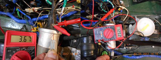
The voltage to coil from the starter relay with ignition in start position was at battery voltage 12.5 V, as it should be. I checked the voltage from the +coil wire that has the voltage reduced via the resistor. I have only 3.67 V, a bit low in my opinion. I think it should be closer to 8 V. I removed the white wire that feeds from the resistor to the coil and checked voltage there. It showed battery voltage 12.5V (see photo). I am pretty sure that if the resistor is good the voltage after going thru the resistor should drop which it failed to do
I again hooked the white wire from the resistor back to the + coil and measured the voltage again………reading did not change ....still 3.67V. See photo I do not think that is as it should be??
Any ideas as to why the voltage tests low on the coil terminal, while the wire prior to be connected to the coil reads 12.5V?
To check for spark, I removed and grounded #1 plug. I then set the rotor to point to the #1 position on the distributor and reinstalled the cap. I turned the ignition switch on and I got a spark (not a good blue spark though) indicating to me that the distributor should be work, I will check the other plugs in a like manner.
Stan from NE
47 wc Dodge pickup
76 midget
1951 Willys Overland PU
I am getting ready for the first start since renewing bearings and thrust washers in the 1500 engine. The electronic Allison ignition is reinstalled. I have not connected the starter cable to the starter relay so I could check starter voltage etc, without the starter spinning.
The voltage to coil from the starter relay with ignition in start position was at battery voltage 12.5 V, as it should be. I checked the voltage from the +coil wire that has the voltage reduced via the resistor. I have only 3.67 V, a bit low in my opinion. I think it should be closer to 8 V. I removed the white wire that feeds from the resistor to the coil and checked voltage there. It showed battery voltage 12.5V (see photo). I am pretty sure that if the resistor is good the voltage after going thru the resistor should drop which it failed to do
I again hooked the white wire from the resistor back to the + coil and measured the voltage again………reading did not change ....still 3.67V. See photo I do not think that is as it should be??
Any ideas as to why the voltage tests low on the coil terminal, while the wire prior to be connected to the coil reads 12.5V?
To check for spark, I removed and grounded #1 plug. I then set the rotor to point to the #1 position on the distributor and reinstalled the cap. I turned the ignition switch on and I got a spark (not a good blue spark though) indicating to me that the distributor should be work, I will check the other plugs in a like manner.
Stan from NE
47 wc Dodge pickup
76 midget
1951 Willys Overland PU
Attachments:
DSCN0681-horz.jpg 36.7 KB

jimbenedict
Jim Benedict
Waterford, MI, USA
Sign in to contact
|
Feb 25, 2017 08:05 PM
Joined 7 years ago
486 Posts
|
|
VoyagerXll
stan schroeder
|
Topic Creator (OP)
Feb 25, 2017 11:13 PM
Joined 13 years ago
318 Posts
|
 |
Feb 26, 2017 07:04 PM
Joined 14 years ago
4,598 Posts
|
What distributor do you have?
The resistor circuit was the feed to the original distributor.
The feed for the coil was a resistor wire.
When you can, post pictures of the whole setup, including the distributor.
If it ain't broke, I'll fix it until it is!
The resistor circuit was the feed to the original distributor.
The feed for the coil was a resistor wire.
When you can, post pictures of the whole setup, including the distributor.
If it ain't broke, I'll fix it until it is!
 |
Feb 26, 2017 07:06 PM
Joined 17 years ago
2,217 Posts
|
 |
Feb 27, 2017 07:06 AM
Top Contributor
Joined 16 years ago
6,280 Posts
|
|
|
Feb 27, 2017 04:56 PM
Joined 14 years ago
4,598 Posts
|
|
VoyagerXll
stan schroeder
|
Topic Creator (OP)
Feb 27, 2017 09:38 PM
Joined 13 years ago
318 Posts
|
We just got home this evening I will be taking readings as suggested and report back . Probably Wednesday as I have a meeting I have to attend tomorrow
Thanks for all of the replies
Stan from NE
47 wc Dodge pickup
76 midget
1951 Willys Overland PU
Thanks for all of the replies
Stan from NE
47 wc Dodge pickup
76 midget
1951 Willys Overland PU
 |
Mar 1, 2017 07:12 AM
Top Contributor
Joined 17 years ago
20,012 Posts
|
The opus distributor runs on 6V via an 11 Ohm resistor before the 1.5 Ohm coil. Any other trigger (points/Pertronix) in the distributor will want 12+V and 3 Ohms of total resistance (internal plus external to the coil.)
jeff@advanceddistributors.com
jeff@advanceddistributors.com
|
VoyagerXll
stan schroeder
|
Topic Creator (OP)
Mar 1, 2017 09:07 AM
Joined 13 years ago
318 Posts
|
Finally I and can get back to the 76 Midget with the 45DE4 distributor that had been converted to the earlier style of the Allison electronic ignition; the one that has a purple, red and black wire exiting the module.
I have been questioning the values my Harbor freight DMM have been giving, so I bought a new "much better" DMM. I am heading to the shop to take some new measurements. Hope to be able to report on them later today.
I have confidence that with help from the forum that we can sort out the strange readings I am getting when measuring voltage to the coil.
Stan from NE
47 wc Dodge pickup
76 midget
1951 Willys Overland PU
|
VoyagerXll
stan schroeder
|
Topic Creator (OP)
Mar 1, 2017 07:45 PM
Joined 13 years ago
318 Posts
|
I rechecked voltages with the new DMM and found that the voltage I had initially reported to be 3.87 V is actually battery voltage around 12.5 V. So apparently I have no resistor?
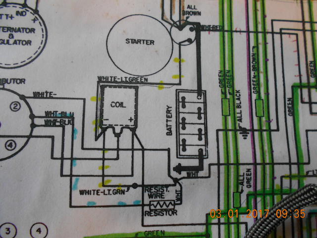
According to the schematic for the 76 Midget, there was originally a white- Lt Green wire going to Coil- as well as connecting to a resist wire. which was also connected to the ignition white wire. (Confused) The previous owner replaced the white-light green wire coming from the starter solenoid going to the coil – with a purple wire (non-resistance). Where was/is the resistance wire located.
There are two different wires exiting the loom ahead of the pedal box, a black/white wire that goes to the tach and a white green wire that I assume feeds the coil? Pic C Should this wire now be the wire that feeds the coil+
The reason I am going through these measurements is to determine if I have a resistor somewhere in the circuit. I seem to remember something about the older Allison XR700 ignition module does not like to operate on bat voltage. I assume since I get the two above mentioned readings that there is no resistor in the run circuit.
The primary resistance of the coil is 1.3 ohms. The distributor is a 45DE4 that has been converted to Allison electronic ignition
Am I correct in thinking that the pictured resistor (pic B) that measured 9.97 is not for the coil,
but rather for the distributor? Pic A shows the Allison X 7000 ign module.
Some where I have pictures on a flash drive of the coil wire orientation when I bought the car and it was running Hope to find them soon.
Main question I now have is how to add a resistor, if in fact one is needed, to protect the coil and what resistance should it be?
Stan from NE
47 wc Dodge pickup
76 midget
1951 Willys Overland PU
Edited 1 time(s). Last edit at 2017-03-02 02:18 PM by VoyagerXll.
Attachments:
DSCN0682.JPG 54.9 KB
|
jimbenedict
Jim Benedict
Waterford, MI, USA
Sign in to contact
|
Mar 1, 2017 08:22 PM
Joined 7 years ago
486 Posts
|
If the coil is 1.3 ohms, then adding a 1.3 ohm resistor would reduce the voltage in half per ohms law or provide 6 volts. However, when a coil is operating, the average voltage is less due to the coil turning on & off. I would guess a 2.2- 2.5 ohm resistor would work.
|
|
Mar 2, 2017 06:54 AM
Top Contributor
Joined 17 years ago
20,012 Posts
|
A standard Chrysler resistor is 1.6-1.7 Ohms.
Your coil is 1.5 Ohms.
10V at the coil while running would indicate a ballast wire is in the harness.
There was never a ballast wire between the coil and starter.
12V+ into the Allison power wire.
3 Ohms between the power wire and the signal wire (coil - terminal)
Ground it well to bare metal.
Chances are good if you're having issues, its because Allison went out of business in the 80's. How many electronics do you use daily from the 80's?
jeff@advanceddistributors.com
|
|
Mar 2, 2017 07:03 AM
Top Contributor
Joined 16 years ago
6,280 Posts
|
|
jimbenedict
Jim Benedict
Waterford, MI, USA
Sign in to contact
|
Mar 2, 2017 08:31 AM
Joined 7 years ago
486 Posts
|
Forums 
Having trouble posting or changing forum settings?
Read the Forum Help (FAQ) or contact the webmaster
